ISV Network Architecture Design and Scaling Options
Independent Software Vendors (ISVs) leverage Oracle Cloud Infrastructure (OCI) to host managed services for their consumers and customers. However, most ISVs have hundreds of consumers and customers which requires a scalable network architecture to meets their requirements.
In this blog, I will discuss how to architect a scalable network architecture to meet the requirements of most ISVs. We will discuss how to futher scale the architecture for very large ISVs as well using OCI’s Dynamic Routing Gateway (DRG) features.
I will also publish a complementary blog on how to integrate DRGs and Local Peering Gateways (LPG) to achieve a scalalable ISV architectures for customers who need isolated DRGs for their remote connectivity. Link will be posted here in the near future.
A Typical Customer VCN Deployment
A typical end customer deployment may consist of a combination of private and public subnets, FastConnect for primary and backup circuits, IPSec tunnels for additional backup scenarios (or possibly as their primary means of connectivity to their compartment), and a DRG as their virtual router for FastConnect, IPSec tunnel, and Virtual Cloud Network (VCN) associations. The diagram below depicts a relatively simple and typical customer design.
However, let’s assume we needed to scale the architecture to support many customers and we wanted to achieve a repeatable pattern while maintaining segregation of customer traffic. This happens to be the case for most ISV architectures and many or all the following design requirements may apply:
ISV Requirements
- ISV’s management VCN must be able to reach every customer VCN to accomplish a single pane of glass to manage all environments
- ISV design should be simple and easy to administer
- ISV could have 100+ customers
- Customers should have access to their resources via VPN or FastConnect
- Customers should not reach or have access to other End Customer VCNs
Considering the requirements above, we can achieve this design leveraging the enhancements provided with the latest DRG updates. If the DRG being used hast not yet been upgraded to support the DRG enhancements, it will need to be upgraded. Information on the DRG upgrade process including the steps on how to upgrade is located here.
Proposed ISV Design
The architecture design in the diagram below depicts the placements for the ISV’s management VCN, the Customer VCNs, and the remote connectivity via FastConnect or IPSec tunnels for both the ISV’s and customer’s remote data centers.
To achieve the architecture, will leverage the following DRG features:
- DRG Route Tables
- DRG Import Lists
- Remote Peering Connections (RPC)
With the features listed above, an ISV can scale up to hundreds and possibly thousands of customers using a repeatable design pattern which is represented in the following diagram:
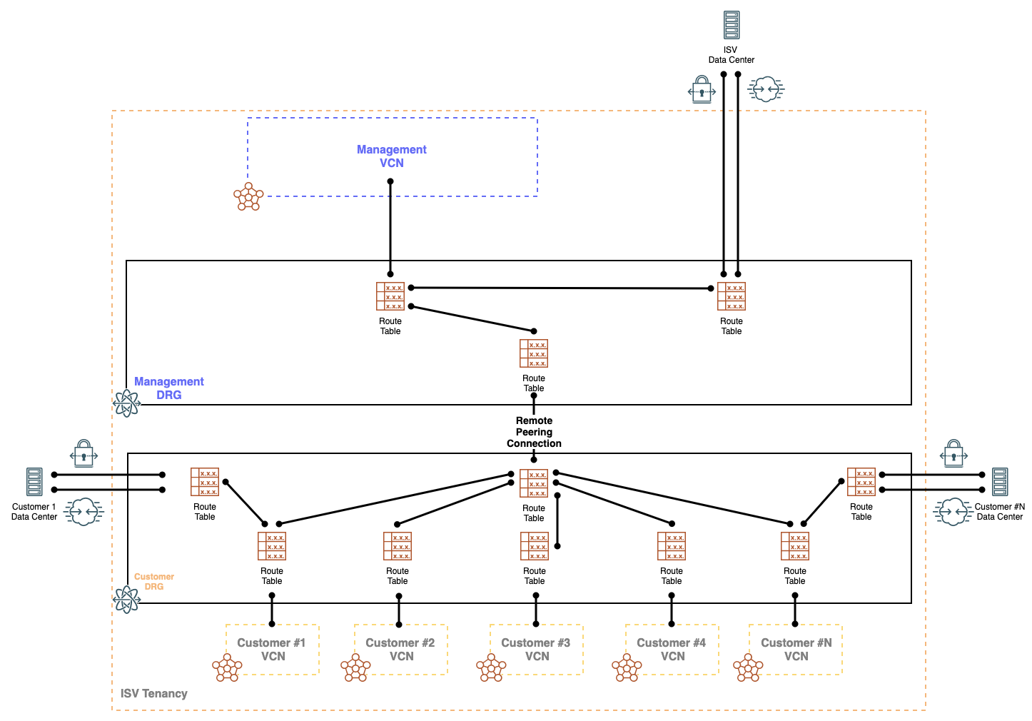
The ISV’s management VCN is attached with its own independent DRG. Likewise, the Customer VCNs are attached with their own shared DRG. The two DRGs will need to be peered using a RPC to establish network connectivity.
While the customer DRG is shared, separation is achieved using unique DRG route tables which have unique import distribution lists associated with them. The association of unique import distribution lists to separate DRG route tables allows for a repeatable and scalable design. This also gives us the ability to explicitly import and propagate specific destination attachments for the ISV management VCN and customer VCNs.
The benefits of unique DRG route tables and distribution lists allow for granular traffic patterns based on per DRG route tables and enhances the security posture by providing segmented routing on a per VCN basis.
In the proposed design, the following import distribution statements are applied:
ISV Management VCN
- Import from the ISV’s FastConnect or IPSec attachment
- Import from RPC attachment used to peer with the customer VCNs
Customer VCNs
- Import from the customer’s FastConnect of IPSec attachment
- Import from the RPC attachment used to peer with the ISV management VCN
Based on the DRG route tables and their associated import distribution lists, we can achieve the following routing patterns:
ISV Management VCN
- The ISV management VCN will have network connectivity to their remote data center
- The ISV management VCN will have network connectivity to all customer VCNs
- The ISV management VCN will not have network connectivity to customer remote data centers
Customer VCNs
- Each customer VCN will have network connectivity to ISV management VCN
- Each customer VCN will have network connectivity to their own remote data center where the appropriate import distribution lists are applied
- This will need to be a mutual distribution in the DRG route tables used by the customer VCN and the customer remote data center
- This will allow Customer A VCN and Customer A FastConnect or IPSec tunnels to only communicate to and from each other while not impacting other customer VCNs and remote data centers
- This will also allow for customer’s remote data centers to have overlapping IP CIDRs without affecting routing within the OCI tenancy
- Overlapping IP addresses are not a recommended practice and can also be overcome using source NAT. However, if ISV’s have customers with overlapping ip addresses in their remote data centers and need access to only their own VCNs, maintaining separate route tables and distribution lists for each customer’s remote connectivity and local VCN can be used and is quicker to implement.
Scaling the Design
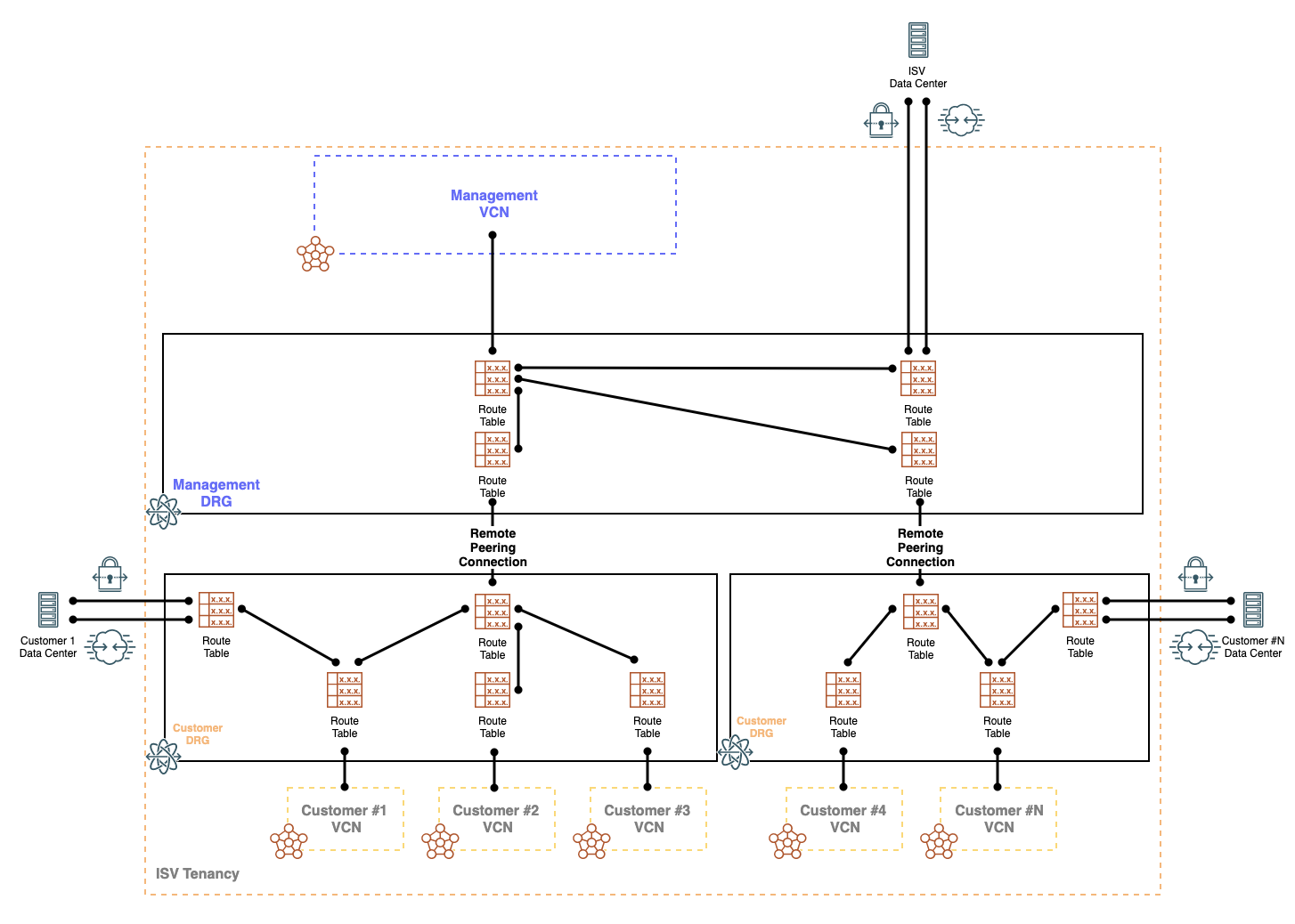
Since we support 300 attachments per DRG, the design can scale up to hundreds of customers. Howeve, we could be suppressed to 100 truely segemented customers within the shared Customer DRG since we currently support a maximum of 100 DRG route tables.
To scale, we can simply repeat the design for the next 100 customers and establish a RPC between the new shared DRG with the ISV management DRG. The architecture design would appear as below:
Design Limitations
While this design can scale to support hundreds of customers, below are a few things to consider:
- Each Dynamic Routing Gateway can have up to 300 VCNs attachments. However, to keep customer traffic truly segmented we will need to leverage the Dynamic Routing Gateway Route Tables which currently have a limit of 100 DRG Route Tables per Dynamic Routing Gateway
- This effectively allows for 100 customers per shared DRG.
- We can always create a new DRG for the next 100 customers and peer the new shared DRG with the ISV management DRG using Remote Peering Connections.
- If you need scale into multiple regions, you will have to rebuild this architecture in each region.
- If you only need one management network globally, you could utilize Remote Peering Connections to peer your management network to a remote region’s infrastructure.
- Be careful with IP address overlap between the ISV and your End Customers
- If IP address overlap exists and connectivity is needed between the ISV management VCN and the Customer VCN, then you must consider using an appliance that performs NAT
- However, as mentioned above, if ISV’s have customers with overlapping ip addresses in their remote data centers and need access to only their own VCNs, maintaining separate route tables and distribution lists for each customer’s remote connectivity and local VCN can be used and is quicker to implement.
- Please note that this design must be used with an upgraded DRG to leverage the enhacements of DRG route tables, DRG distribuition lists, and multiple attachments to the DRG.
I will also publish a complementary blog on how to integrate DRGs and Local Peering Gateways (LPG) to achieve a scalalable ISV architectures for customers who need isolated DRGs for their remote connectivity. Link will be posted here in the near future.
References
Dynamic Routing Gateway Documentation