Welcome to part 2 of the OCI-Azure Interconnect advanced scenarios.
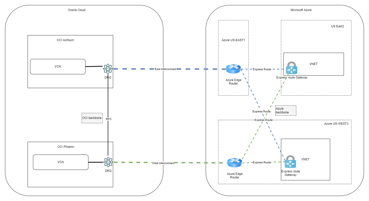
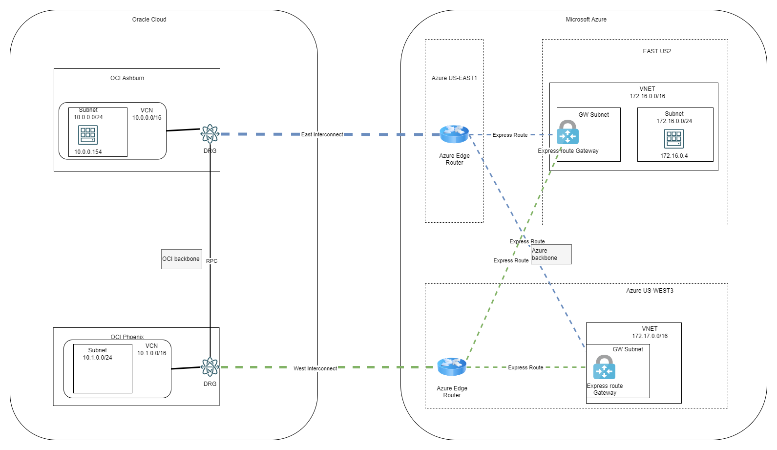
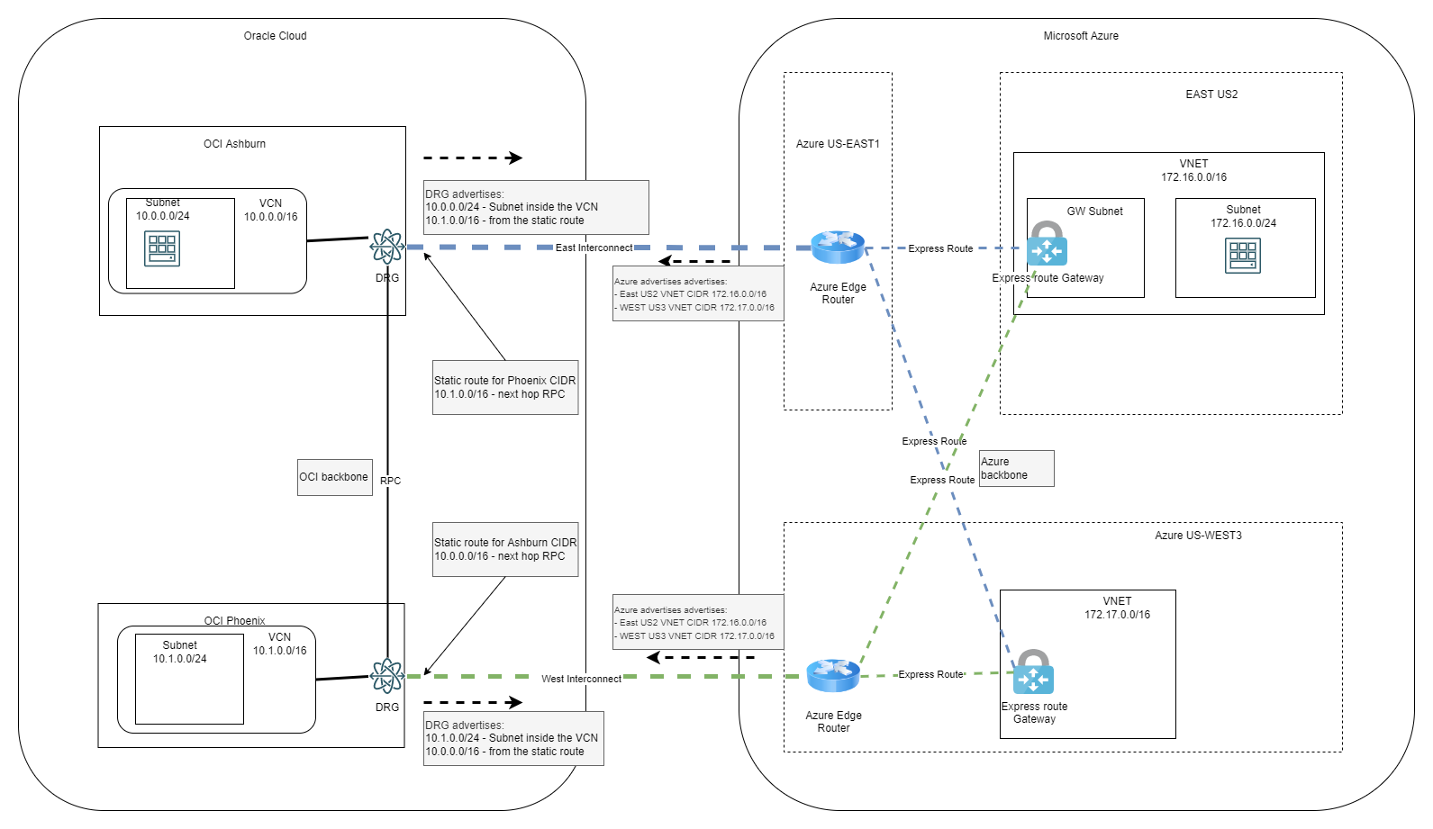
In part 1 we discussed a few concepts and challenges while in this entry we will focus on a demo for the architecture below:
1. Deploy OCI and Azure initial resources
In the interest of not making this entry very long we will not go into details for every step, but rather focus on the parts that are tricky.
OCI
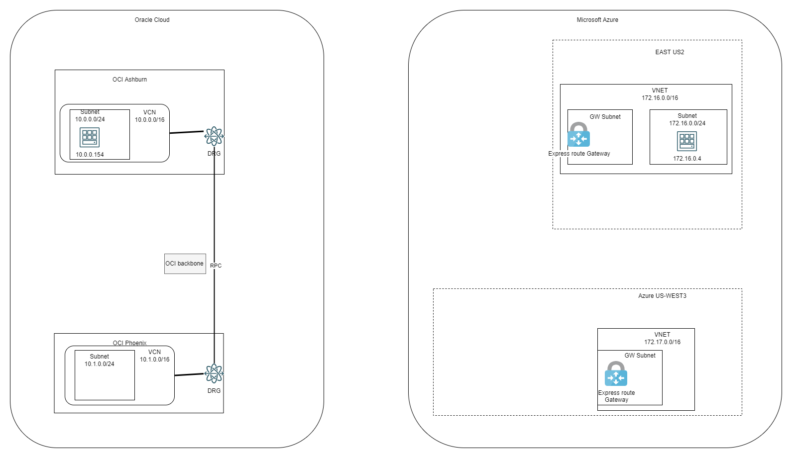
In OCI, the following constructs have been built:
- Ashburn:
- One VCN with one subnet inside
- One DRG
- The VCN was connected to the DRG with the default settings*
- One Compute Instance inside the subnet in the VCN
- Phoenix:
- One VCN with one subnet inside
- One DRG
- The VCN was connected to the DRG with the default settings*
- One RPC Connection between Ashburn and Phoenix
Note: When we connect a VCN to a DRG, the DRG will advertise, by default, the individual subnets inside the VCN, not the VCN CIDR. We will use this later on, in the demo.
Azure
In Azure, the following constructs have been built:
- East US2:
- One VNET
- One Gateway subnet and one VPN Gateway
- One Subnet for a compute instance
- One compute instance
- West US3
- One VNET
- One Gateway subnet one VPN Gateway
At this stage the Lab looks like this:
2. Add Interconnect
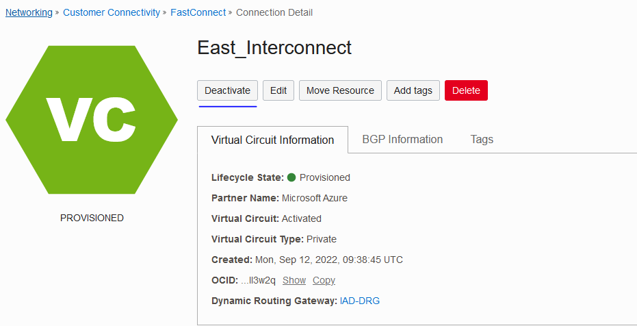
The next step is to add 2 Interconnect link between OCI and Azure:
- OCI Ashburn to Azure US East1 – we will call it East Interconnect
- OCI Phoenix to Azure US West 3 – we will call it West Interconnect
I will not provide the steps here, please follow the steps in this excellent blog entry: Step-by-step-guide-to-build-interconnect
Remember that the ExpressRoute SKU has to be Standard.
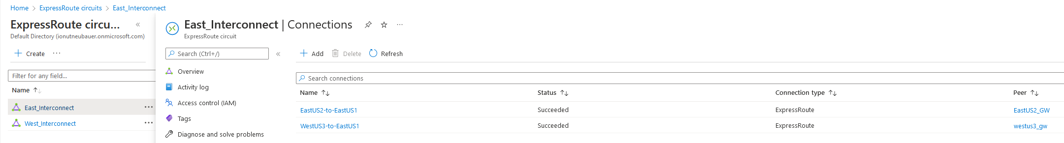
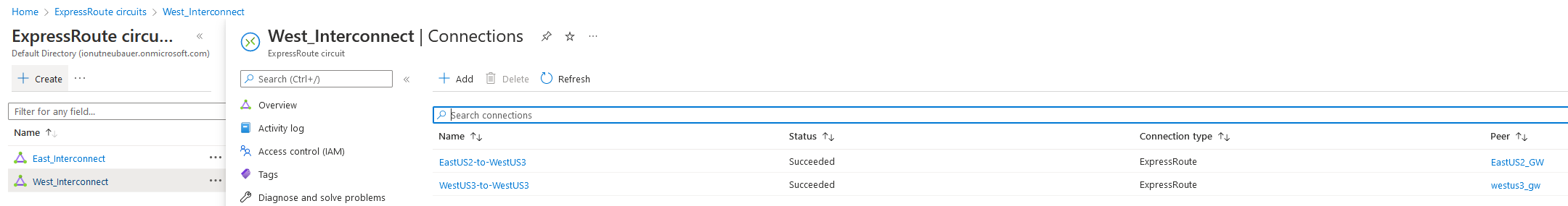
After both Links are UP, we need to add the VPN Gateways connections to the Circuits. In each circuit we will add both VPN Gateways, from East US2 and West US3, as below:
With the Circuits in place and the Connections between VPN Gateways and the Circuits, the diagram will now look like below:
With all the connections in place, let’s see what each cloud learns about the other related to routing.
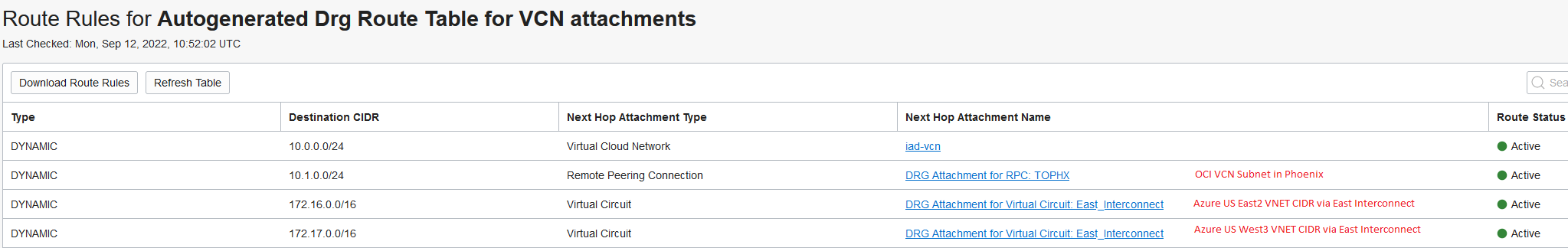
OCI DRG routing details
Ashburn:
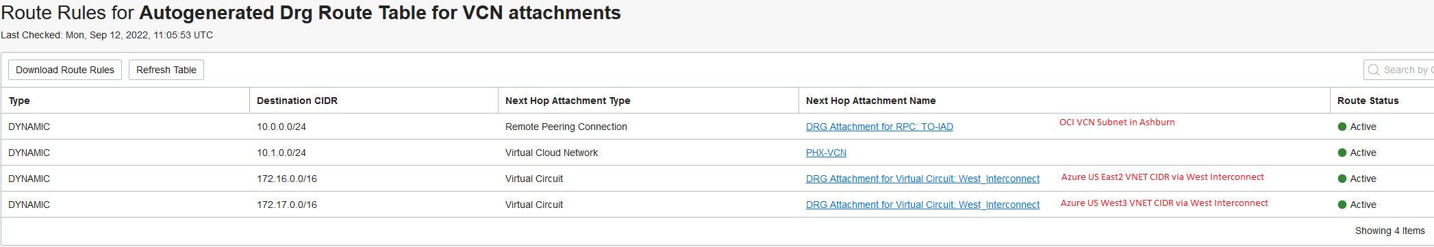
Phoenix:
Azure routing details
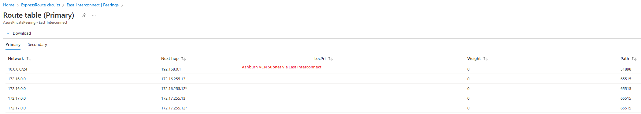
East Circuit:
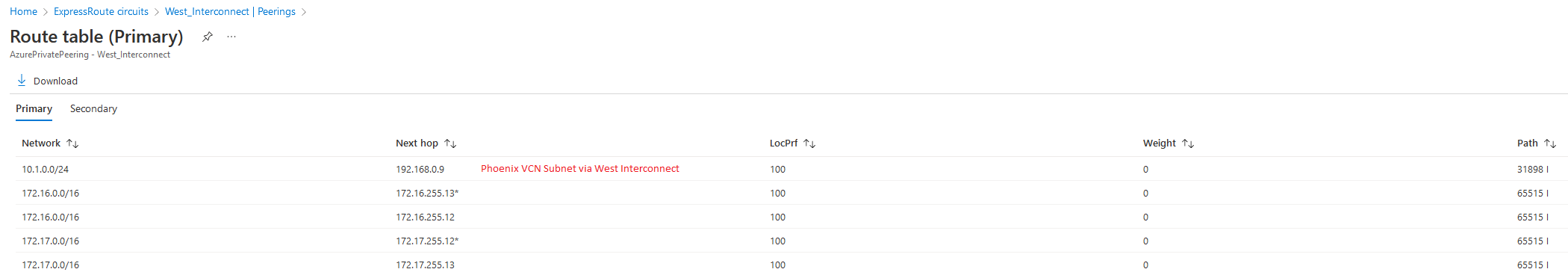
West Circuit:
Compute Instance in US East2 routing table:
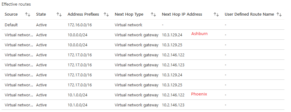
So, at this stage, OCI Ashburn can only “see” Azure US East2 and OCI Phoenix can only “see” Azure US West3. The compute instance in Azure US East2 can connect to both OCI Ashburn and OCI Phoenix because the VPN Gateway is connected to both Circuits but if any of the Interconnect links have issues the connection will stop. Let’s improve that by adding another layer of redundancy. We will make each Interconnect act as a backup for the other.
3. Enabling redundancy
In Azure there is no action needed because we linked both VPN Gateways to both circuits in a full Mesh.
In OCI we have to do two things:
a.Configure the RPC to work with FastConnect links.
Go to the RPC DRG Route table and click it:
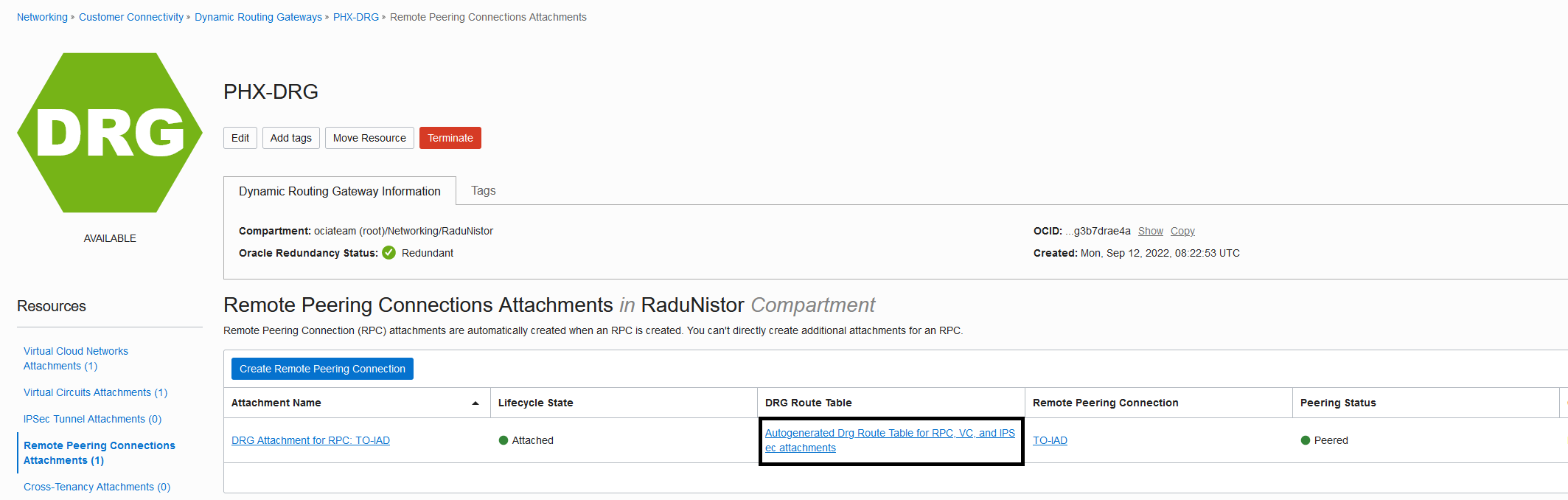
Next, click the import distribution list:
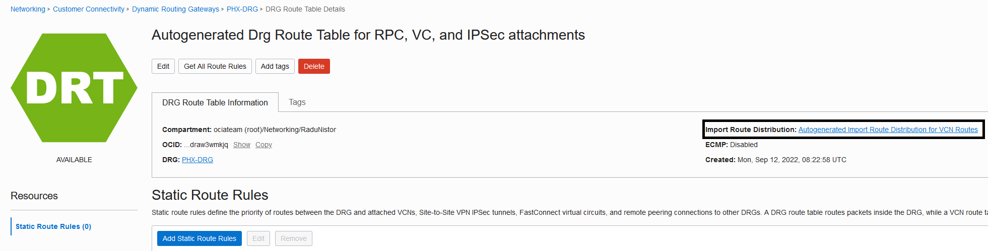
Add the following Route Distribution statement:
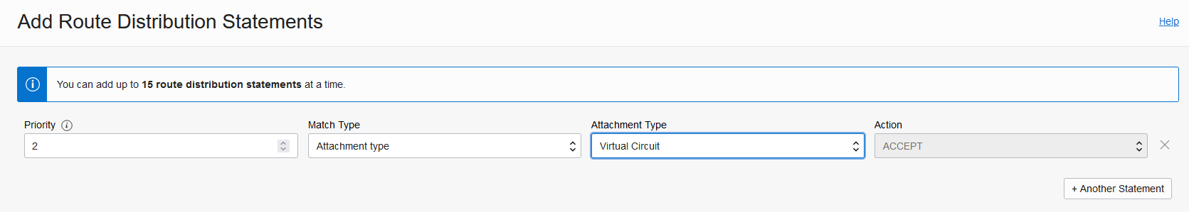
Note: Do this procedure on both regions, Ashburn and Phoenix.
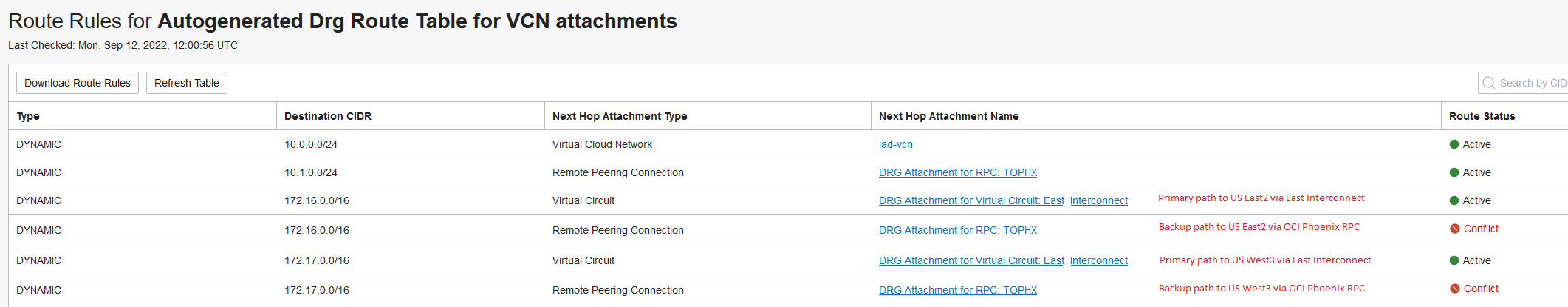
b.We have to advertise on Interconnect in each OCI region less preferred routes for the other region. For example, in Ashburn we will advertise the Phoenix VCN CIDR (10.1.0.0/16) which is less preferred than the Phoenix VCN Subnet (10.1.0.0/24). The way to manually advertise subnets over the FastConnect is to put static route entries in the FastConnect DRG Route Table.
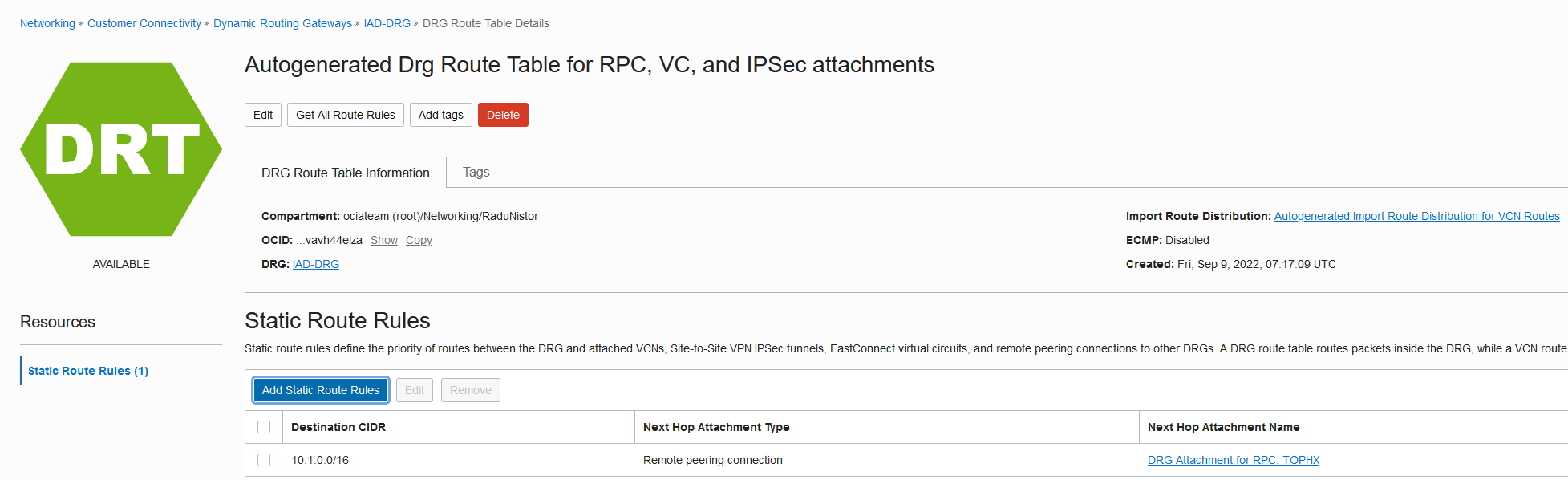
Go to the Ashburn FastConnect DRG Route table and click it:

Add a static entry for the Phoenix VCN CIDR (the /16) next-hop the RPC:
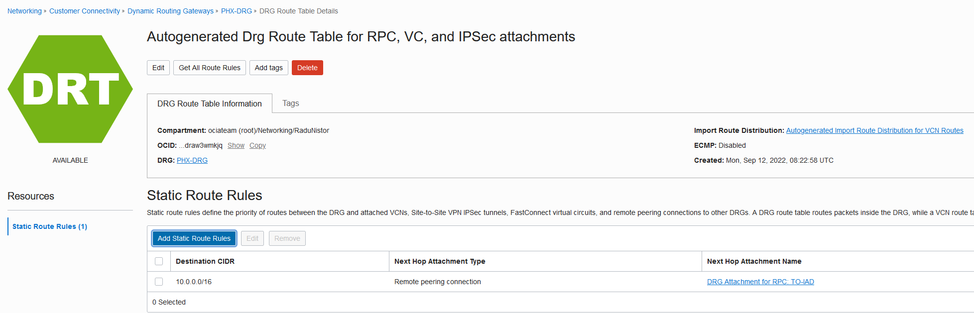
Repeat the same process for the Phoenix Interconnect. The static route should look like this:
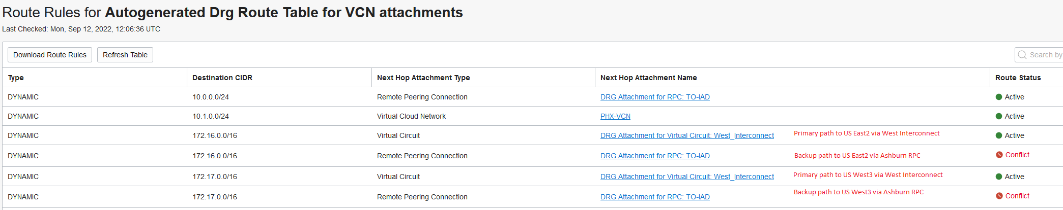
Now let’s check the new routing information in both clouds.
OCI
Ashburn:
Phoenix:
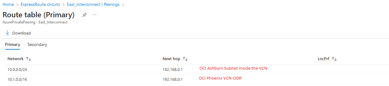
Azure
East Interconnect:
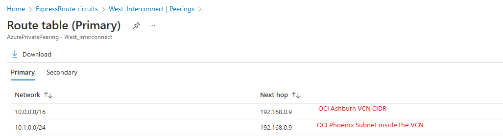
West Interconnect:
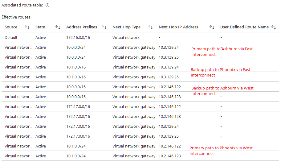
Compute actual routing:
Let’s add all this info to the diagram:
And there you have it, a redundant multi-region OCI-Azure Interconnect.
4. Redundancy test
One last thing is to test the redundancy. Let’s see a ping from Azure to OCI:
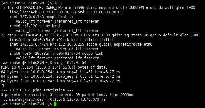
As both Compute Instances are in the same region ( Ashburn/US East2) the latency is 6ms.
Let’s simulate a failure of the East Interconnect. We can do that by deactivating the circuit on OCI’s side:
Within seconds the flow rerouted via the backup path. Note that if the actual circuit fails the rerouting will take longer due to BGP timers. In our case, the “deactivate” initiated a graceful shutdown.
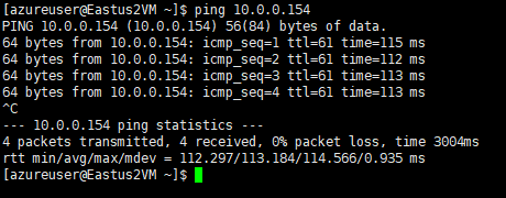
Notice that the latency jumped to 113 ms due to the fact the packet has to travel from Azure US East2 to US West3 then to OCI Phoenix and back to OCI Ashburn. It is not ideal but there is no service interruption.
Conclusion
By using various networking constructs from both OCI and Azure we managed to create a fully redundant multi-region network architecture.
