ISV Architecture Design and Scaling Options Using Local Peering Gateways and Dynamic Routing Gateways
In the previous ISV Architecture Design and Scaling Options blog, we discussed how to design and scale an ISV Cloud Network Architecture leveraging the enhanced Dynamic Routing Gateway (DRG) native features such as DRG route tables and DRG import lists. While this design is proven and can scale for most ISVs, there are some cases where the ISV customers need to leverage their own DRG for additional security and compliance controls to prevent unintentional route leaks from the various customer Virtual Cloud Networks (VCN) and from customer on-premises locations.
In this case, we can leverage a combination for DRG attachments for the ISV VCN attachment and Transit VCNs with Local Peering Gateways (LPG) to each customer VCN for customer VCN isolation purposes. The customer VCN will have the ability to attach to their own customer dedicated DRG for connectivity to their on-premises locations while maintaining connectivity to the ISV cloud managed VCN.
A Typical Customer VCN Deployment
A typical customer deployment may consist of a combination of privat and public subnets. FastConnect for primary and backup circuits, IPSec tunnels for additional back scenarios (or possibly as their primary means of connectivity), and a DRG as their virtual route for FastConnect, IPSec tunnel, and VCN associations.
However, let’s assume we needed to scale the architecture to support many customers and we wanted to achieve a repeatable pattern while maintaining segregation of customer traffic. This happens to be the case for most ISV architectures and many or all the following design requirements may apply:
ISV Requirements
- ISV’s management VCN must be able to reach every customer VCN to accomplish a single pane of glass to manage all environments
- ISV design should be simple and easy to administer
- ISV could have 100+ customers
- Customers should have access to their remote sites via dedicated DRGs using FastConnect or IPSec tunnels
- Customers should not reach or have access to other customer VCNs or other customer remote sites
Considering the requirements above, we can achieve this design leveraging a combination of the enhancements provided with the latest DRG updates and LPG connections. If the DRG being used has not yet been upgraded to support the DRG enhancements, it will need to be upgraded for the DRGs used by the ISV VCNs (not necessarily the DRGs used by the customer VCN). Information on the DRG upgrade process including the steps on how to upgrade is located here.
Proposed ISV Design
In this design’s simplest form, the architecture should adhere to the following technical guidelines:
- The customer VCNs will connect to a Transit VCN using LPG connections
- The customer VCN will connect to its own dedicatged DRG for remote site connectivity
- The Transit VCN will attach to the Transit DRG
- The ISV Management VCN will attach to the Management DRG
- The Transit DRG and the Management DRG will connect using a Remote Peering Connection (RPC) to each other
Below is a network diagram representing of the network topology described above:

Considerations
There are several things to consider in this hybrid DRG + LPG design. We will discuss the following aspects related to this design:
- Routing
- Scaling
- Security
- Limitations
Routing
Unlike the DRG native ISV Network Architecture, the DRG + LPG architecture will have multiple routing destinations to use from the customer VCNs perspective. Specifically, we will need to leverage the LPG via the Transit VCN for network connectivity towards the ISV Management VCN and the customer dedicated DRG for network connectivity towards the customer’s on-premises locations. Let’s take a look into how the network connectivity and reachability is achieved with the various componenets.
From the customer VCN’s perspective, network connectivity and reachability is achieved using the following:
- 0.0.0.0/0 (or specific remote site CIDRS) via the customer dedicated DRG towards the customer’s on-premises locations
- ISV Management VCN CIDR via the LPG towards the Transit VCN
From the Transit VCN’s perspective, network connectivity and reachability is achieved using the following:
- Customer VCNs CIDRs via the respective LPG connections
- ISV Management VCN CIDR via the Transit DRG
From the Transit DRG perspective, network connectivity and reachability is achieved using the following:
- RPC connection between the Transit DRG and the Management DRG
- DRG route table for the RPC attachment and a separate DRG route table for the Transit VCN attachment with mutual route propagation using DRG distribution lists and DRG route tables
From the Management DRG perspective, network connectivity and reachability is achieved using the following:
- RPC connection between the Transit DRG and the Management DRG’
- ISV Management CIDRs via the Management VCN attachment
- A DRG route table for the RPC attachment and a DRG route table for the ISV Management VCN attachment with mutual route propagation using DRG distribution lists and DRG route tables
- A DRG route table for the FastConnect attachment and a DRG route table for the ISV Management VCN attachment with mutual route propagation using DRG distribution lists and DRG route tables
- Note: We can use a single DRG route table for the ISV Management VCN attachment since we will need to import both the FastConnect CIDRs and the RPC connection CIDRs
From the ISV Management VCN’s perspective, network connectivity and reachability is achieve using the following:
- Customer VCNs CIDRs via the DRG
- ISV remote site CIDRS via the DRG
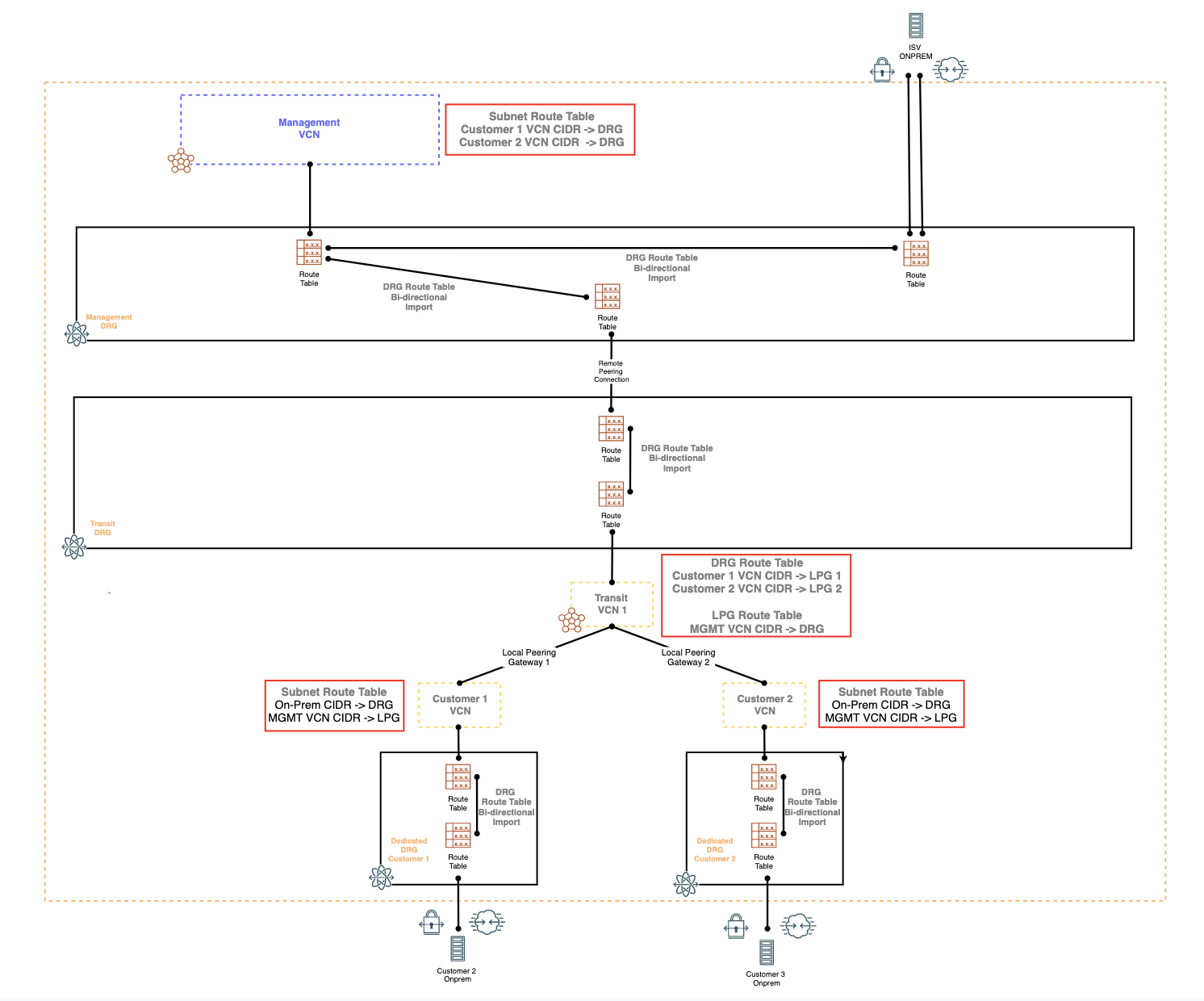
With regards to routing for the Transit VCN, there will need to be a unique VCN route table associated with each LPG connection. Additionally, the Transit VCN DRG attachment will need to have its own unique VCN route table as well and the DRG attachment and the VCN route table must be assocaited with each other in order to route transitively through the Transit VCN (please refer to the Transit Routing Documentation for additional information regarding trasitive routing in OCI). The LPG route table will have a single route towards the ISV Management VCN CIDR via the DRG. The VCN route table used by the DRG will need to have route statements towards the customer VCN CIDRs via their respective LPG attachments.
Below is a diagram of the same topology in Figure 1 with the route tables and the corresponding route statements:
Scaling
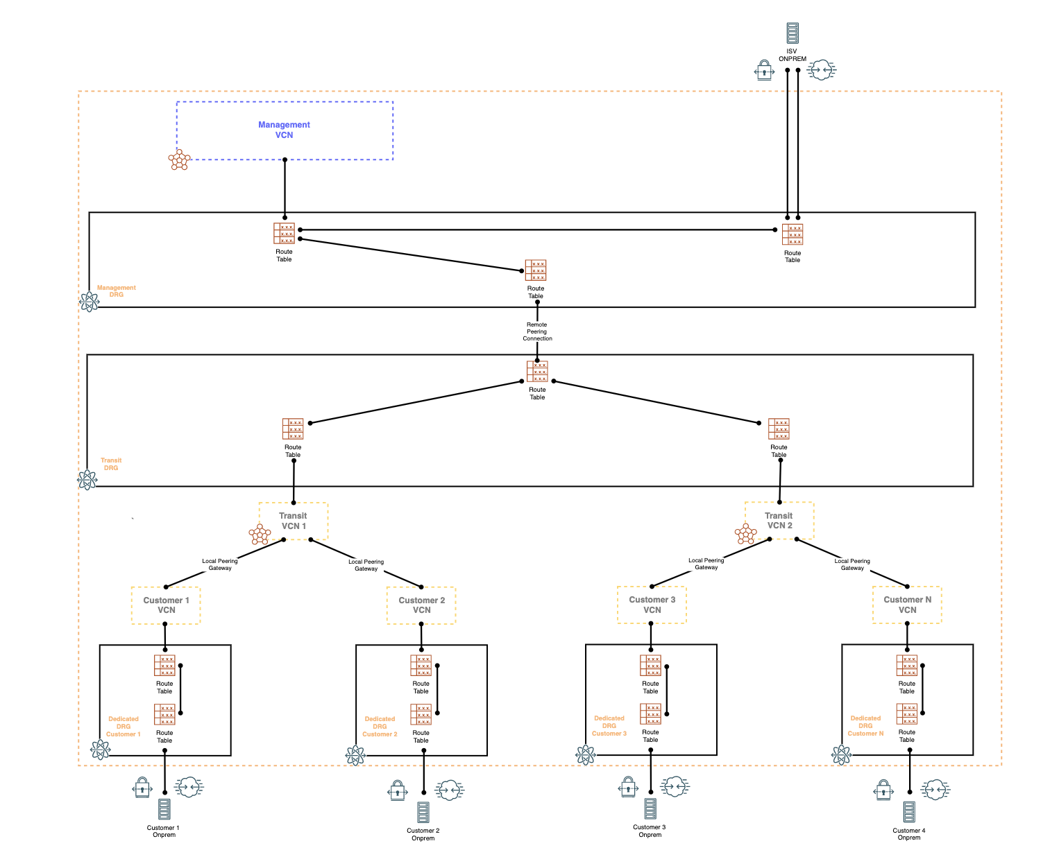
Since the amount of LPG connections are limited to 10 LPG connections per VCN, we are limited to supporting a maximum of 10 customer VCN LPG connections per Transit VCN. To scale the design, we will need to scale the Transit VCN’s horizontally.
The following diagram depicts how to scale the design using horizontally scaled Transit VCNs:
Security
This specific design limits the exposure of potential customer routing leakage (typically due to DRG misconfiguration) in the DRG native design since the customers VCNs are isolated to their own DRG. The only other alternate route is towards the ISV management VCN via the LPG connection.
Design Limitations
The primary limitations using this design are the default service limits we have on items such as LPG connections and the number of DRGs per region. LPG connections are limited to 10 LPG connections per VCN. While the LPG connections limits can be increased slightly, it cannot scale to the 300 DRG VCN attachments as described in the previous ISV Architecture Design and Scaling Options blog.
In addition, we will need to account for service limits for the number of DRGs supported per region (by default, we support 5 DRGs per region per tenancy and limits can be increased). Please discuss this archtecture option with an OCI Cloud Architect prior to deploying.
References
Local Peering Gateway Documentation