1. Introduction
OCI is offering to ISV customers a way to accommodate hundreds of end customers. The solution together with the implementation is described in a series of blogs that can be analyzed following the link: https://www.ateam-oracle.com/isv-architecture-operations
However, in a given POD we can have one customer using VCN CIDR range that can overlap with the ISV Management VCN. In the ISV Management VCN, the administrator can place VMs that need to access all the customers VCNs for monitoring purposes or just for the customers to be able to access shared services and resources. If the CIDR ranges between Mgmt VCN and any end customer VCN the communication will not happen.
In the following chapters, we will follow the solution proposed for the communication between overlapping CIDR to occur.
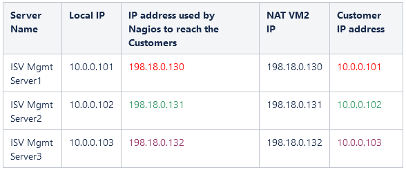
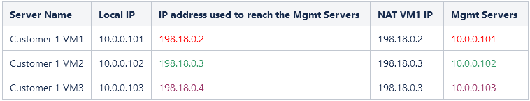
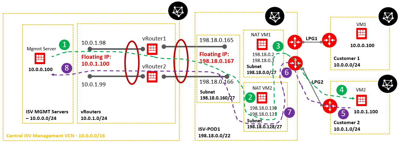
An ISV has multiple management servers sitting in a “shared subnet”. Mgmt Server 1 – with IP 10.0.0.101, Mgmt Server 2 – 10.0.0.102, Mgmt Server 3 – 10.0.0.103 and so on. On the other hand, the customers VCNs in some scenarios can contain VMs with 10.0.0.101, 10.0.0.102, 10.0.0.103 etc. as IP address. Our goal is to make the IP connectivity between Mgmt servers from the “shared subnet” to talk with the customer VMs with the same IP addresses as the Mgmt servers.
In order to have a working solution, we need to instruct either the Mgmt Servers that the Customers have a different unique IP address and vice-versa. The following table is summarizing an example of a unique IP address plan used in the NAT policies. Please follow the step-by-step examples listed in section 4 for any details regarding the NAT configuration.
In the below tables we have summarized some examples on how we can treat the communication.
Traffic from Mgmt servers to Customers:
Traffic from Customers to Mgmt Servers:
Note: The solution proposed should be used as a temporary solution. Every NAT solution implies an overhead in the configuration and maintenance and may introduce in heavily used networks, some degree of latency. The final solution should consider using for each and every end customer a unique/non-overlapping IP address space. For example, the range of 198.18.0.0/15 can be used. For more information related to 198.18.0.0/15 address space follow the link: https://www.iana.org/assignments/iana-ipv4-special-registry/iana-ipv4-special-registry.xhtml
In our solution, we will use two NAT VMs, one NAT VM exposed to the customer side, and another one exposed to the Mgmt Servers VCN.
The reasons for using two NAT VMs are:
Please refer to the networking topology at point two and consider we are using just NAT VM1.
- without using different routing tables (VRF Lite) on a Linux VM we cannot expose the VM to two different destination networks having the same IP prefix even if we are using two vnics in different subnets – this will translate in having two routes to the same destination (10.0.0.0/24) in the Linux routing table as per the networking diagram from point two. The Linux VM will load-balance the traffic which is not the intended behavior in our case;
- if we use one vnic on the Linux VM, OCI will not permit two routes to the same destination by using different next-hops (an LPG and a private IP in our case). NAT VM1 will be exposed to the Customer 1 VCN which is 10.0.0.0/24 and to ISV Mgmt servers which is 10.0.0.0/24, the same IP Prefix. This means for NAT VM1 to reach either of the networks we should have two routes in the routing table associated with the NAT VM1 vnic1: route to Customer 1 VCN (10.0.0.0/24) via LPG and a route to Mgmt Servers VCN (10.0.0.0/24) via 198.18.0.167. However, the OCI is not permitting to have a route in the same routing table associated with a subnet the same route by going to two different next-hops.
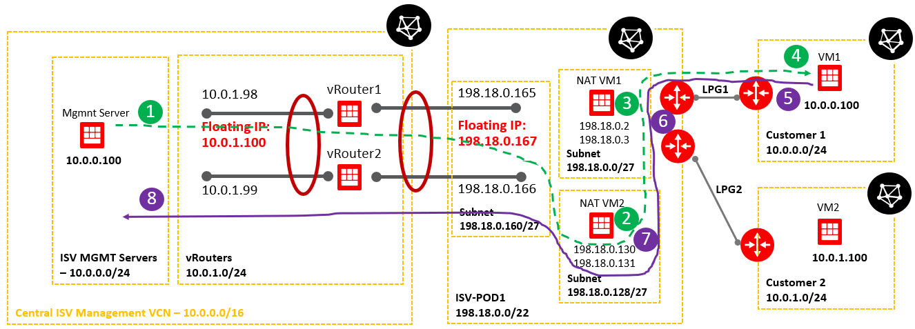
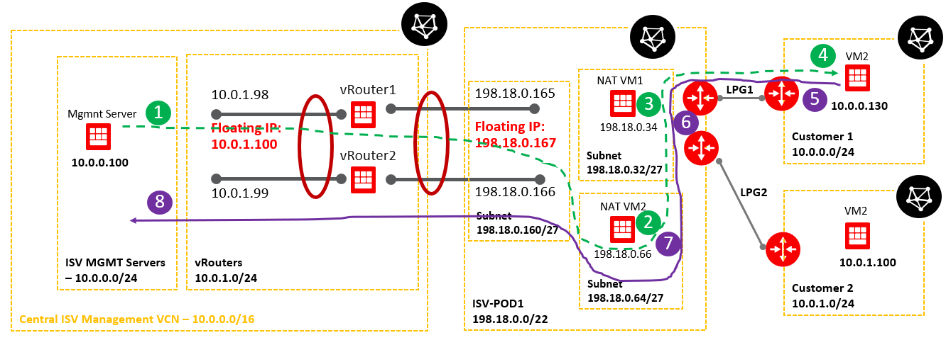
2. Networking topology
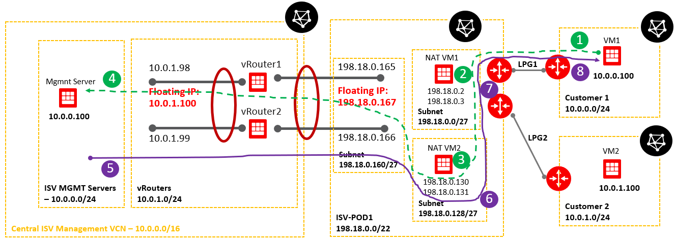
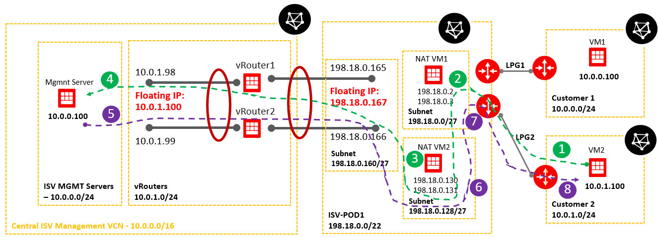
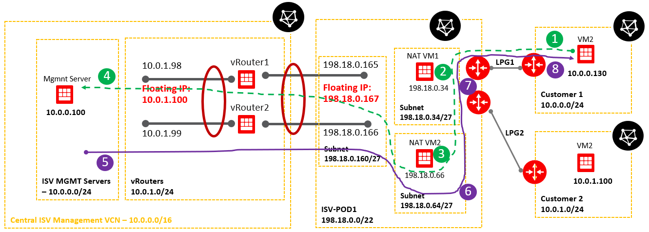
Below is a simplified networking topology reflecting one POD.
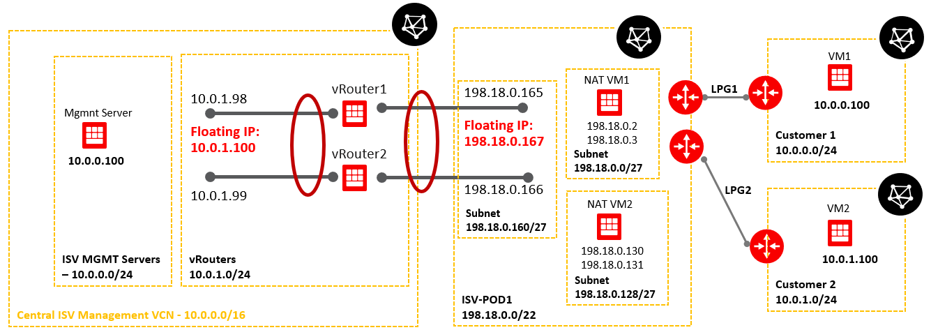
As we can see, both customer VCNs are overlapping with the ISV Mgmt Servers VCN. We need to address this issue and permit the communication from VM1 and VM2 to Magmnt Server and from Mgmt Server as traffic originator to VM1 and VM2.
Prerequisites:
- In a given POD the customer VCNs should not overlap;
- In a given POD for NAT we will use two VMs in two different subnets;
- Based on point 2, any POD (for the subnets where the vRouter floating IP and NAT VMs are provisioned) should have uniques CIDR defined from the range of 198.18.0.0/15 for accommodating the proper and correct routing;
- On both NAT VMs edit
/etc/sysctl.confand insert:
net.ipv4.ip_forward=1
# the IP forward will activate the forwarding function on a Linux VM (it will act as a router when the traffic needs to be sent from one interface over another or just route the traffic out using the same interface where the traffic has been received)
net.ipv4.conf.all.rp_filter = 0
net.ipv4.conf.ens*.rp_filter = 0
# the rp_filter is needed in our topology to let the Linux VM to forward the traffic received on one interface over another interface based on the routing table entry: for example, the traffic is received on ens5 but the outgoing interface after packet processing is ens3; For more details regarding rp_filter please follow the link: https://access.redhat.com/documentation/en-us/red_hat_enterprise_linux/6/html/security_guide/sect-security_guide-server_security-reverse_path_forwarding
Usesudo sysctl -pto read the values from file.
Replace the red star with the vnic number except for your first interface.
As an example: consider your first vnic is ens3 and your secondary vnics are ens5 and ens6. You need to add in the sysctl.conf:net.ipv4.conf.ens5.rp_filter = 0;net.ipv4.conf.ens6.rp_filter = 0
After each change on the sysctl.conf file make sure you use sudo sysctl -p to read the values from the file.
- Make sure that all the VNICs on the NAT VM1 and NAT VM2 have the SKIP SOURCE/DESTINATION CHECK enabled on the OCI WebUI;
- Disable the NAT VM1 and NAT VM2 internal firewall with the command
systemctl disable firewalldand reboot the VMs; - After disabling the firewall please make sure the correct Security Lists or NSGs are configured to secure the traffic to/from the NAT VMs;
3. Solution scalability
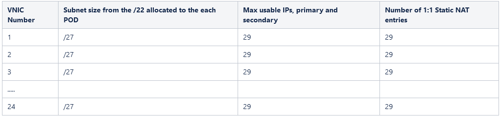
Consider below numbers for a 2.24 VM shape:
- If we consider a 2.24 VM this will offer up to 24 interfaces;
- On one interface we can have up to 31 secondary IP addresses from a particular subnet, so in order to accommodate all 31 IP addresses we need to have at least a subnet with 61 usable hosts (we will subtract the subnet id, default gateway and broadcast) -> this means we will lose a lot of IPs;
- The new approach: we will consider subnets with 32 IPs and from the 32 IPs we will use just 29 IPs (subtract one for subnet id, one for default gateway and one for broadcast) – this means we will have 28 secondary IP addresses plus the primary one = 29 on a single interface;
- According to 3, we can create up to 29 static 1-1 NAT entries;
- For simplicity we can use a unique /22 from 198.18.0.0/15 to define the VCN CIDR for NAT in each and every POD;
- From the /22 we will define /27 subnets for up to 32 subnets (8×4) to accommodate all the 24 interfaces that can be added to a 2.24 VM shape and a /29 subnet to accommodate the virtual router in the POD;
- The /22 will let us configure POD NAT VCNs in up to 128 PODs having overlapping CIDR with the ISV Management VCN;
The above 1-4 points are summarized in the following table for a 2.24 NAT VM shape:
4. NAT VMs configuration
4.1 NAT VM1 and VM2 subnet routing table configuration
NAT VM1:

NAT VM2:
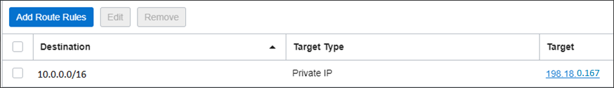
As we can see from the routing tables configured above, NAT VM1 has connectivity to the customer VCNs via respective LPGs and NAT VM2 IP connectivity to the ISV Mgmt Servers using the vRouter floating IP as a next-hop. This is the reason we need two NAT VMs, with just only one we cannot handle the routing in a correct manner -> using just one VM it will be exposed to the same destination network 10.0.0.0/16 with two different next hops. This is not allowed in OCI. Even we create a second vnic in another subnet we will face issues with the routing at the VM level.
ISV Mgmt VCN needs to have access only to 198.18.0.128/27 and not to 198.18.0.0/27, we will analyze in the next sub-section related to VM1 and VM2 NAT configuration why this statement is true.
4.2 NAT VM1 and VM2 iptables NAT configuration
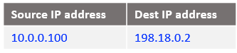
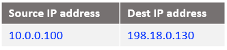
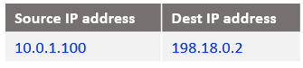
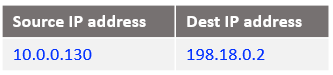
Case 1: Analyzing the traffic path originated by Customer 1 VM1 (10.0.0.100) to the Mgmt Server at 10.0.0.100 and the response from the Mgmt Server.
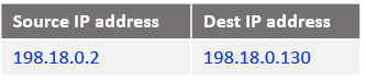
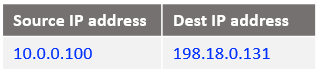
In order for the traffic from Customer 1 VM1 (formerly VM1) to work, we need to send it to an IP destination address different than 10.0.0.100 (assigned to the Mgmt Server as well). The destination IP address used will be 198.18.0.2.
The green dashed line represents the traffic path originated by VM1 toward Mgmt Server.
The purple solid line represents the traffic path for the response sent by the Mgmt Server to VM1.
At step 1:
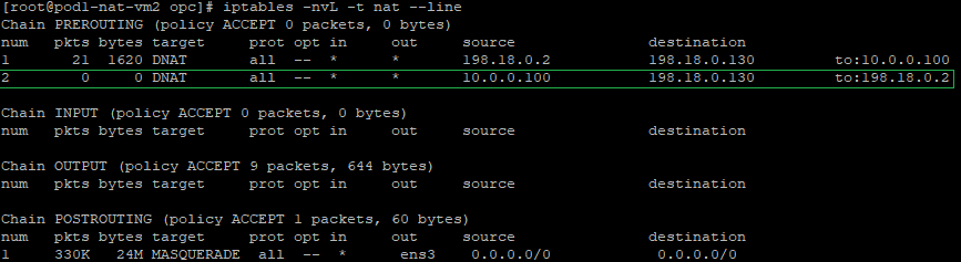
At step 2 some interesting operations are happening at the NAT VM1 level:
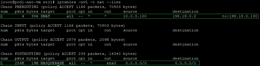
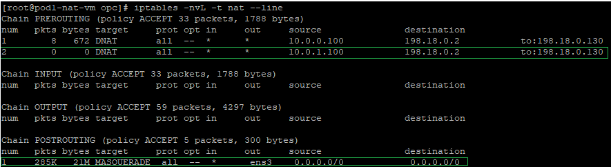
a) create a DNAT (Destination NAT) entry in the iptables PREROUTING NAT chain – the DNAT entry is necessary because we need to change the destination IP address from 198.18.0.2 to 198.18.0.130 where the final forwarding toward the Mgmt Server will be done, the command is:
iptables -t nat -A PREROUTING -s 10.0.0.100 -d 198.18.0.2 -j DNAT --to-destination 198.18.0.130
The above command is having the following logic: if the source IP address of the incoming packet is 10.0.0.100 and the destination IP address is 198.18.0.2 change the destination IP from 198.18.0.2 to 198.18.0.130 (the second NAT VM) and route the packet. The conclusion we draw is this entry is analyzed before the routing process (hence the PREROUTING chain) because we are changing the destination IP address.
b) In order for the source IP address of VM1 (10.0.0.100) to not appear in the IP packet arriving at the NAT VM2, we will NAT all source IP addresses from the customers side at the NAT VM1 using its primary IP address, which is 198.18.0.2, the command is:
iptables -t nat -A POSTROUTING -o ens3 -j MASQUERADE
The above command will replace any source IP address forwarded out on ens3 interface with the primary IP address of ens3 interface, 198.18.0.2.
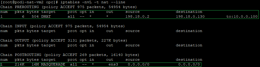
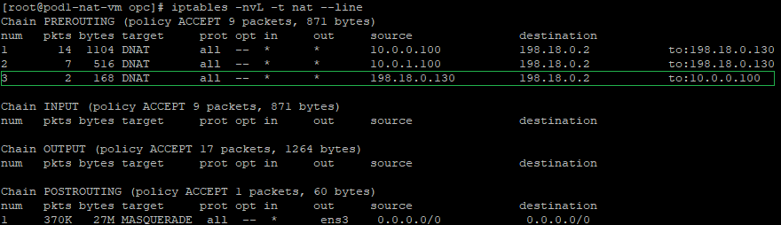
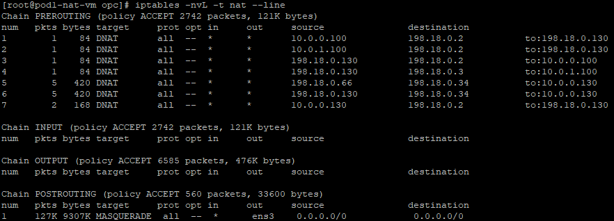
The final verification will imply to check the NAT tables and see if the configuration has been inserted, the command to use: iptables -nvL -t nat --line
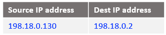
c) The IP packet format sent out by the NAT VM1 to NAT VM2 after all NAT processing:
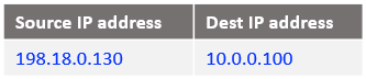
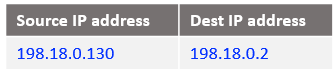
At step 3 let’s see what is happening when the traffic arrives at NAT VM2.
a) create a DNAT entry and change the destination IP address from 198.18.0.130 to 10.0.0.100 which is the Mgmt Server in the Magmnt ISV VCN. We can see this NAT VM2 is exposed only to the Mgmt VCN CIDR range. The command:
iptables -t nat -A PREROUTING -s 198.18.0.2 -d 198.18.0.130 -j DNAT --to-destination 10.0.0.100
The above command is having the following logic: if the source IP address of the incoming packet is 198.18.0.2 and the destination IP address is 198.18.0.130 change the destination IP from 198.18.0.130 to 10.0.0.100 (the Mgmt Server IP) and route the packet. The conclusion we draw is this entry is analyzed before the routing process (hence the PREROUTING chain) because we are changing the destination IP address.
b) In order for the source IP address of NAT VM1 (198.18.0.2) to not appear in the IP packet arriving at the Mgmt Server, we will NAT all source IP addresses that need to be forwarded out over ens3 interface at the NAT VM2 using its primary IP address, which is 198.18.0.130, the command is:
iptables -t nat -A POSTROUTING -o ens3 -j MASQUERADE
The final verification will imply to check the NAT tables and see if the configuration has been inserted, the command to use: iptables -nvL -t nat --line
c) The packet format sent out by the NAT VM2 after all NAT processing:
The packet is routed using as next-hop the floating IP address (198.18.0.167) of the vRouter.
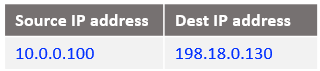
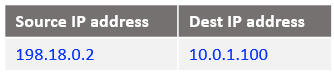
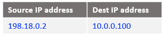
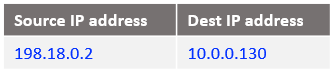
At step 4: The packet arrives at the Mgmt Server in the below form:

At step 5: This is the beginning of Mgmt Server response to Customer1 VM1, the IP packet has the following form when reaches NAT VM2:
At step 6: NAT VM2 already has this connection tracked at step 3 when it has received the IP packet and processed by the DNAT rule. Will only reverse the source and the destination IPs, the IP packet is listed below:

At step 7: NAT VM1 already has this connection tracked at step 2 when it has received the IP packet and processed by the DNAT rule. Will only reverse the source and the destination IPs, the IP packet is listed below:

At step 8: the IP packet at step 7 reaches the VM1 containing the response from the Mgmt Server.

Case 2: Analyzing the traffic path originated by Customer 2 VM2 (10.0.1.100) to the Mgmt Server at 10.0.0.100 and the response from the Mngmt Server.
Let’s suppose in this case we are not performing any NAT and we are sending the traffic directly to 10.0.0.100 from 10.0.1.100. When the Mgmt Server responds, the traffic will be sent directly to the VIP of the Virtual Server (10.0.1.100) even if the virtual server was not the originator of the traffic. In networking terms, this can be considered a flood with traffic on the vRouter. In any case, the response will not reach VM2.
In order for the traffic from Customer 2 VM2 (formerly VM2) to work, we need to send it to an IP destination address different than 10.0.0.100 (assigned to the Mgmt Server) to avoid any routing issues in the ISV Mgmt VCN tacking into account that Customer 2 VCN overlaps with 10.0.0.0/16 assigned to the ISV Mgmt VCN. The destination IP address used will be 198.18.0.2, the same as in Case 1.
Let’s follow the same logic.
The green dashed line represents the traffic path originated by VM2 toward Mgmt Server.
The purple solid line represents the traffic path for the response sent by the Mgmt Server to VM2.
At step 1:

At step 2: following the logic from Case 1, create the following DNAT entry in the NAT VM1:
iptables -t nat -A PREROUTING -s 10.0.1.100 -d 198.18.0.2 -j DNAT --to-destination 198.18.0.130
The above command is having the following logic: if the source IP address of the incoming packet is 10.0.1.100 and the destination IP address is 198.18.0.2 change the destination IP from 198.18.0.2 to 198.18.0.130 (the second NAT VM) and route the packet. The conclusion we draw is this entry is analyzed before the routing process (hence the PREROUTING chain) because we are changing the destination IP address.
Let’s check to see if the new NAT entry has been added:
The IP packet format sent out by the NAT VM1 to NAT VM2 after all NAT processing:

At step 3 let’s see what is happening when the traffic arrives at NAT VM2.
In Case 1 step 3 we have included a DNAT entry in the NAT VM2 that is performing the following: if the source IP address of the incoming packet is 198.18.0.2 and the destination IP address is 198.18.0.130 change the destination IP from 198.18.0.130 to 10.0.0.100 (the Mgmt Server IP) and route the packet.
This step becomes really simple, by making sure any traffic from the customer side reaching NAT VM2 has the same source IP address (198.18.0.2, by using the NAT Masquerade) with just one DNAT entry we can send to 10.0.0.100 any traffic with the source IP address of 198.18.0.2. All the traffic sent for the customers VCNs to Magmnt Servers will use the same 198.18.0.2 as the source IP address when reaching NAT VM2.
The IP packet format sent out by the NAT VM2 after all NAT processing:

At step 4: The packet arrives at the Mgmt Server in the below form:

At step 5: This is the beginning of Mgmt Server response to Customer2 VM2, the IP packet has the following form when reaches NAT VM2:

At step 6: NAT VM2 already has this connection tracked at Case 2 step 3 when it has received the IP packet from NAT VM1 and processed by the DNAT rule. Will only reverse the source and the destination IPs, the IP packet is listed below:
At step 7: NAT VM1 already has this connection tracked at Case 2 step 2 when it has received the IP packet from VM2 and processed by the DNAT rule. Will only reverse the source and the destination IPs, the IP packet is listed below:
At step 8: the IP packet at step 7 reaches the VM1 containing the response from the Mgmt Server.

In Linux we can see the NAT-ed sessions, all we need to do is to verify the content of the file located at: /proc/net/nf_conntrack
Now, we have two different hosts talking to the Mgmt Server, let’s check how the nf_conntrack is looking for icmp:

With the red color are the streams initiated from the customer side and with the green are the responses based on the NAT processing. Please note the IDs which are unique for each and every session. This will be the session diferentiator.
Case 3: Analyzing the traffic path originated by ISV Mgmt VM (10.0.0.100) to the Customer 1 VM1 at 10.0.0.100 and the response from VM1.
The green dashed line represents the traffic path originated by Mgmt Server toward VM1.
The purple solid line represents the traffic path for the response sent by the VM1 to Mgmt Server.
At step 1:
In order for the traffic from Mgmt Server (10.0.0.100) to work, we need to send it to an IP destination address different than 10.0.0.100 (assigned to the VM1 as well). The destination IP address used will be 198.18.0.130. This IP address is assigned to the NAT VM2 vnic.
The IP packet format:
At step 2 some interesting operations are happening at the NAT VM2 level:
a) create a DNAT (Destination NAT) entry in the iptables PREROUTING NAT chain – the DNAT entry is necessary because we need to change the destination IP address from 198.18.0.130 to 198.18.0.2 where the final forwarding toward the VM1 will be done, the command is:
iptables -t nat -A PREROUTING -s 10.0.0.100 -d 198.18.0.130 -j DNAT --to-destination 198.18.0.2
The above command is having the following logic: if the source IP address of the incoming packet is 10.0.0.100 and the destination IP address is 198.18.0.130 change the destination IP from 198.18.0.130 to 198.18.0.2 (the first NAT VM) and route the packet. The conclusion we draw is this entry is analyzed before the routing process (hence the PREROUTING chain) because we are changing the destination IP address.
In order for the source IP address of Mgmt Server (10.0.0.100) to not appear in the IP packet arriving at the NAT VM1, we will NAT all source IP addresses from the Mgmt ISV side at the NAT VM2 using its primary IP address, which is 198.18.0.130. This is done by using the NAT Masquerade statement defined above.
The final verification will imply to check the NAT tables and see if the configuration has been inserted, the command to use: iptables -nvL -t nat --line
b) The IP packet format sent out by the NAT VM2 to NAT VM1 after all NAT processing:
At step 3 let’s see what is happening when the traffic arrives at NAT VM1.
a) create a DNAT entry and change the destination IP address from 198.18.0.2 to 10.0.0.100 which is the VM1 in the Customer 1 VCN. Remember that NAT VM1 is exposed only to the customer VCNs.
iptables -t nat -A PREROUTING -s 198.18.0.130 -d 198.18.0.2 -j DNAT --to-destination 10.0.0.100
The above command is having the following logic: if the source IP address of the incoming packet is 198.18.0.130 and the destination IP address is 198.18.0.2 change the destination IP from 198.18.0.2 to 10.0.0.100 (the VM1 IP) and route the packet.
Using the NAT Masquerade statement already configured the traffic arrives at VM1 with a source IP address of 198.18.0.2.
b) The IP packet format sent out by the NAT VM1 to Customer 1 VM1 after all NAT processing:

At step 4: The packet arrives at the VM1 in the below form:
At step 5: This is the beginning of VM1 response to Mgmt VM, the IP packet has the following form when reaches NAT VM1:

At step 6: NAT VM1 already has this connection tracked at step 3 when it has received the IP packet and processed by the DNAT rule. Will only reverse the source and the destination IPs, the IP packet is listed below:

At step 7: NAT VM2 already has this connection tracked at step 2 when it has received the IP packet from Mgmt VM and processed by the DNAT rule. Will only reverse the source and the destination IPs, the IP packet is listed below:

At step 8: the IP packet at step 7 reaches the Mgmt Server containing the response from the VM1.

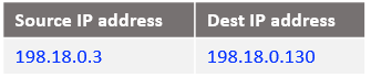
Case 4: Analyzing the traffic path originated by ISV Mgmt VM (10.0.0.100) to the Customer 2 VM2 at 10.0.1.100 and the response from VM2.
The green dashed line represents the traffic path originated by Mgmt Server toward VM2.
The purple solid line represents the traffic path for the response sent by the VM2 to Mgmt Server.
At step 1:
In order for the traffic from Mgmt Server (10.0.0.100) to work, we need to send it to an IP destination address different than 10.0.1.100 (assigned to the VM2). If we will use directly 10.0.1.100 IP address as destination, the floating IP of the vRouter will receive it at Layer 3 which is not the intended destination. The destination IP address used will be 198.18.0.131, a secondary IP address on the NAT VM2 vnic.
The IP packet format:
At step 2 some interesting operations are happening at the NAT VM2 level:
a) create a DNAT (Destination NAT) entry in the iptables PREROUTING NAT chain – the DNAT entry is necessary because we need to change the destination IP address from 198.18.0.131 to 198.18.0.3 (a secondary IP address on the NAT VM1 vnic) where the final forwarding toward the VM1 will be done, the command is:
iptables -t nat -A PREROUTING -s 10.0.0.100 -d 198.18.0.131 -j DNAT --to-destination 198.18.0.3
The above command is having the following logic: if the source IP address of the incoming packet is 10.0.0.100 and the destination IP address is 198.18.0.131 change the destination IP from 198.18.0.131 to 198.18.0.3 (the first NAT VM secondary IP) and route the packet.
In order for the source IP address of Mgmt Server (10.0.0.100) to not appear in the IP packet arriving at the NAT VM1, we will NAT all source IP addresses from the Mgmt ISV side at the NAT VM2 using its primary IP address, which is 198.18.0.130. This is done by using the NAT Masquerade statement defined above.
The final verification will imply to check the NAT tables and see if the configuration has been inserted, the command to use: iptables -nvL -t nat --line
b) The IP packet format sent out by the NAT VM2 to NAT VM1 after all NAT processing:
At step 3 let’s see what is happening when the traffic arrives at NAT VM1.
a) create a DNAT entry and change the destination IP address from 198.18.0.3 to 10.0.1.100 which is the VM2 in the Customer 2 VCN.
iptables -t nat -A PREROUTING -s 198.18.0.130 -d 198.18.0.3 -j DNAT --to-destination 10.0.1.100
The above command is having the following logic: if the source IP address of the incoming packet is 198.18.0.130 and the destination IP address is 198.18.0.3 change the destination IP from 198.18.0.3 to 10.0.1.100 which is the Customer 2 VM2. All traffic reaching NAT VM1 from NAT VM2 will have as a source IP address of 198.18.0.130 from the NAT Masquerade on the NAT VM2.
b) The IP packet format sent out by the NAT VM1 to Customer 1 VM1 after all NAT processing:
At step 4: The packet arrives at the VM2 in the below form:

At step 5: This is the beginning of VM2 response to Mgmt VM, the IP packet has the following form when reaches NAT VM1:
At step 6: NAT VM1 already has this connection tracked at step 3 when it has received the IP packet and processed by the DNAT rule. Will only reverse the source and the destination IPs, the IP packet is listed below:
At step 7: NAT VM2 already has this connection tracked at step 2 when it has received the IP packet from Mgmt VM and processed by the DNAT rule. Will only reverse the source and the destination IPs, the IP packet is listed below:

At step 8: the IP packet at step 7 reaches the Mgmt Server containing the response from the VM2.
4.3 Adding more VNICs after all 29 secondary IP addresses on a vnic are exhausted for 1:1 NAT entries
Let’ suppose that we have up to 29 1:1 NAT statements defined above, in other words, we need to create a second vnic on NAT VM1 and NAT VM2 in order to accommodate another 29 1:1 NAT entries.
For the new vnics we will define two /27 subnets in the following way: 198.18.0.32/27 for NAT VM1 second vnic and 198.18.0.64/27 for NAT VM2 second vnic, as below:
[root@pod1-nat-vm opc]# ifconfig
ens5: flags=4163<UP,BROADCAST,RUNNING,MULTICAST> mtu 1500
inet 198.18.0.34 netmask 255.255.255.224 broadcast 0.0.0.0
[root@pod1-nat-vm2 opc]# ifconfig
ens5: flags=4163<UP,BROADCAST,RUNNING,MULTICAST> mtu 1500
inet 198.18.0.66 netmask 255.255.255.224 broadcast 0.0.0.0
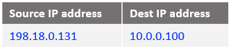
Case 5: In Customer 1 VCN we will create another VM that needs access to the ISV Mgmt VM. The new VM will have the IP address of 10.0.0.130 as below:
[root@cust1-vm2 opc]# ifconfig
ens3: flags=4163<UP,BROADCAST,RUNNING,MULTICAST> mtu 9000
inet 10.0.0.130 netmask 255.255.255.128 broadcast 10.0.0.255
We will maintain the same logic as in our previous traffic flow examples and for the sake of the networking diagram, we will illustrate only this case to keep it as clean as possible (the other IPs used in the previous examples are on the NAT VM but not exemplified here).
The green dashed line represents the traffic path originated by Customer 1 VM2 toward ISV Mgmt Server.
The purple solid line represents the traffic path for the response sent by the ISV Mgmt Server to Customer 1 VM2.
At step 1 the packet format is the following:
We can see for this direction we are not changing anything, we are just using the same destination IP address as in the previous cases for simplicity.
At step 2 we need to instruct NAT VM1 to handle in a unique way this packet by inserting a DNAT rule as below:
iptables -t nat -A PREROUTING -s 10.0.0.130 -d 198.18.0.2 -j DNAT --to-destination 198.18.0.130
Following the logic, if the source IP address is 10.0.0.130 and the destination 198.18.0.2 change the destination IP address to 198.18.0.130 and route the IP packet. After all NAT processing on NAT VM1 the IP packet sent to NAT VM2 is:

At step 3 the NAT entry is already inserted and we do not need to perform any action on the NAT VM2.
At step 4 the IP packet sent out by the NAT VM2 after all NAT processing is:

At step 5: ISV Magmnt Server responds to the Customer 1 VM2 and the IP packet has the following form:

At step 6: NAT VM2 already has this connection tracked at step 3 and the IP packet sent out to NAT VM1 is:

At step 7: NAT VM1 already has this connection tracked at step 2 and the IP packet sent out toward Customer1 VM1 is:

At step 8: The IP packet arrives at Customer 1 VM2:
Case 6: ISV Mgmt VM access to Customer 1 VM2
Using the networking diagram listed below we will analyze this case.
The green dashed line represents the traffic path originated by ISV Mgmt Server toward Customer 1 VM2.
The purple solid line represents the traffic path for the response sent by the Customer 1 VM2 to ISV Mgmt Server.
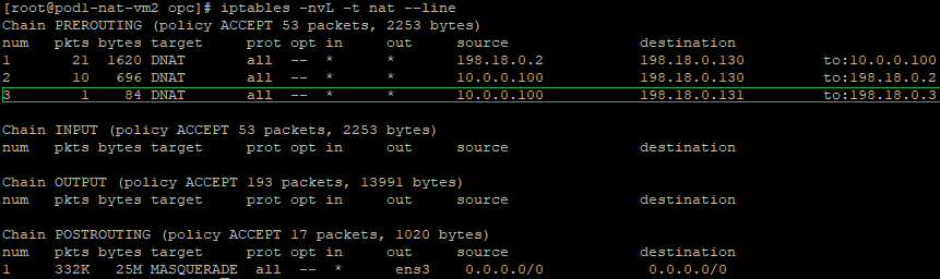
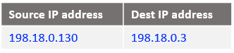
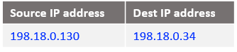
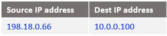
At step 1 we will use as a destination IP address 198.18.0.66, the newly defined IP address on NAT VM2 second vnic. The IP packet reaching NAT VM2 has the following form:
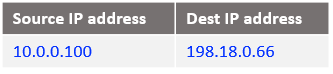
At step 2, when the IP packet is reaching NAT VM2 we need to redirect this packet to NAT VM1. For this purpose, we will include the following DNAT rule:
iptables -t nat -A PREROUTING -s 10.0.0.100 -d 198.18.0.66 -j DNAT --to-destination 198.18.0.34
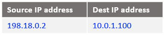
With the above rule, we will match exactly a new pair of IP addresses between NAT VM2 and NAT VM1 to uniquely match the traffic for 10.0.0.130. If the source IP address is 10.0.0.100 and if the destination is 198.19.0.66 change the destination IP address to 198.18.0.34 and route the packet. Taking into account that NAT VM2 is performing a NAT Masquerade on the ens3 vnic which is the outgoing interface, the IP packet that is reaching NAT VM1 has the following form:
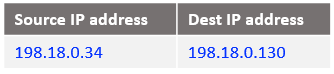
At step 3, when the IP packet is reaching NAT VM1 we need to redirect this packet to Customer 1 VM2. For this purpose, we will include the following DNAT rule:
iptables -t nat -A PREROUTING -s 198.18.0.130 -d 198.18.0.34 -j DNAT --to-destination 10.0.0.130
Taking into account that NAT VM1 is performing a NAT Masquerade on the ens3 vnic which is the outgoing interface, the IP packet that is reaching Customer 1 VM2 has the following form:

At step 4, the IP packet is reaching Customer 1 VM2:

At step 5: This is the beginning of Customer 1 VM2 response to Mgmt VM, the IP packet has the following form when reaches NAT VM1:

At step 6: NAT VM1 already has this connection tracked at step 3 and the IP packet sent out to NAT VM2 is:
At step 7: NAT VM2 already has this connection tracked at step 2 and the IP packet sent out toward ISV Mgmt VM is:

At step 8: The IP packet arrives at ISV Mgmt VM:
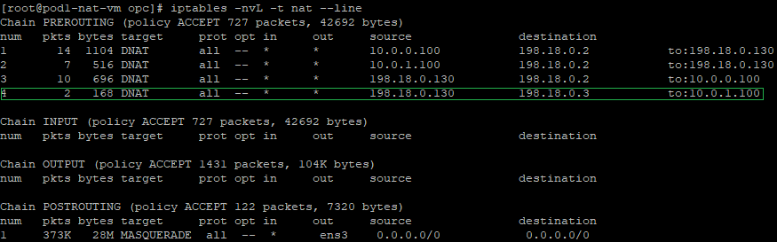
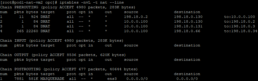
At the end of our examples the NAT tables are configured in the following way for the above use cases:
NAT VM1:
NAT VM2:
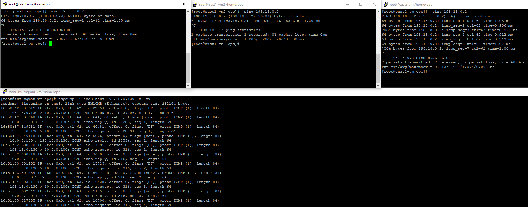
5. Traffic testing
5.1 ICMP from Customer 1 VM1 and VM2 + Customer 2 VM2 toward ISV Mgmt Server
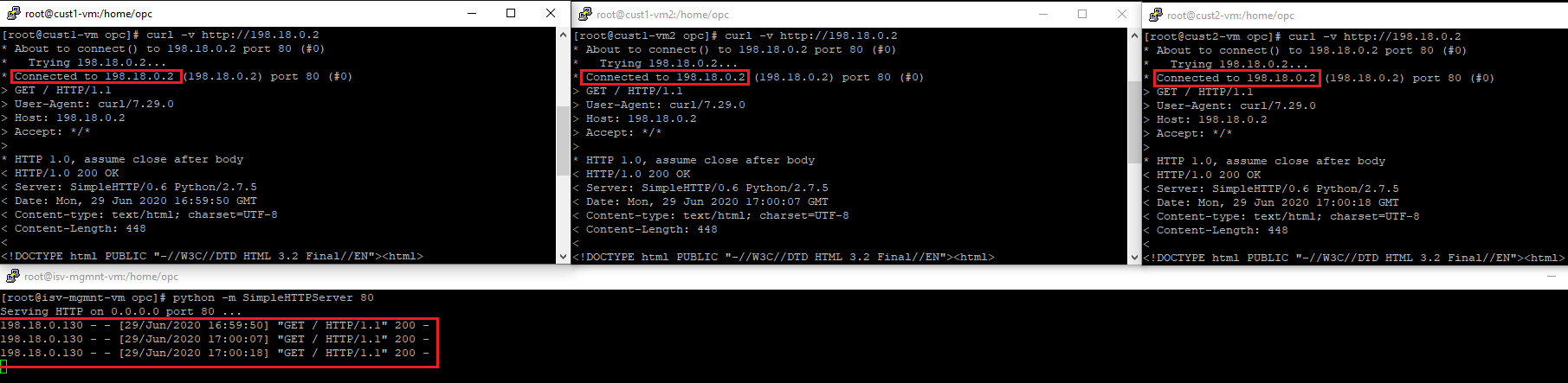
5.2 HTTP traffic from Customer 1 VM1 and VM2 + Customer 2 VM2 toward ISV Mgmt Server
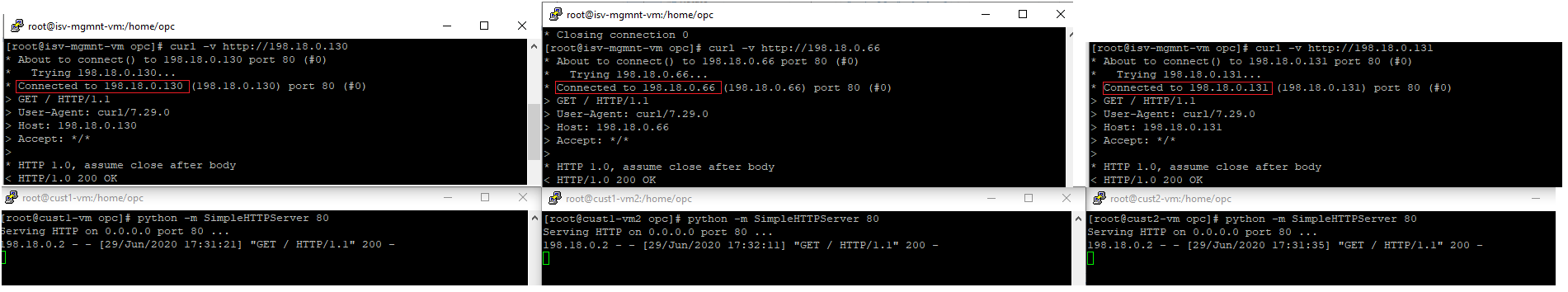
For this part, we will start a simple http server on the Mgmt Server.
5.3 ICMP traffic from ISV Mgmt Server toward Customer 1 VM1 and VM2 + Customer 2 VM2
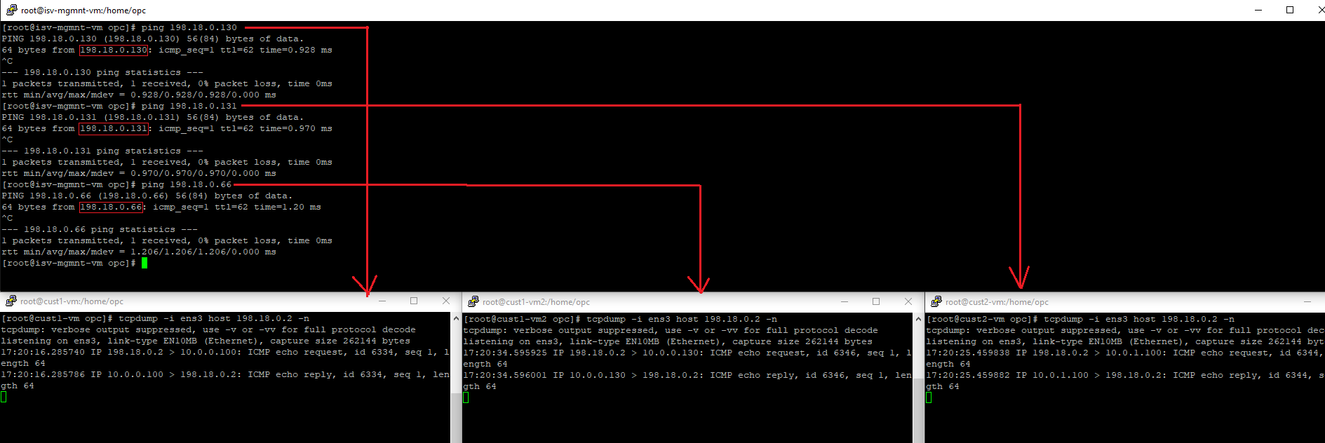
5.4 HTTP traffic from ISV Mgmt Server toward Customer 1 VM1 and VM2 + Customer 2 VM2
6. Save the iptables configuration to persists if the NAT VMs are restarted
After you have performed the NAT configuration let’s proceed to save the configuration to be persistent if any of the NAT VMs are going to be rebooted.
6.1 Install iptables-services: yum install iptables-services
6.2 Save the iptables entries you have created: iptables-save > /etc/sysconfig/iptables
6.3 Enable the iptables service: systemctl enable iptables
6.4 Start the iptables service: systemctl start iptables
Now, if the VMs are restarted you should have all the entries in the NAT table.
Note: Every time when a NAT entry is added or changed make sure you save it with iptables-save > /etc/sysconfig/iptables.