1. Introduction
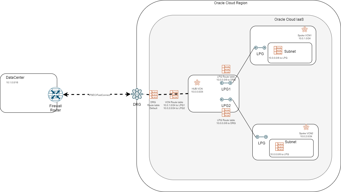
One of the most common architectures in OCI is the hub-and-spoke design. Until last year the only way to implement it was using Local Peering Gateways which connected Spokes to a HUB VCN which, in turn, was attached to a Dynamic Routing Gateway to provide connectivity from the client datacenters to the OCI environment.
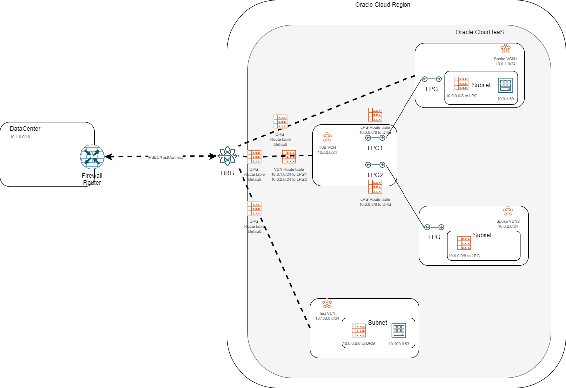
A common architecture can be seen in the picture below:
With the introduction of The Enhanced DRG, we can now implement this design in a different way, by making the DRG the “hub” and all other VCNs as spokes, as below:
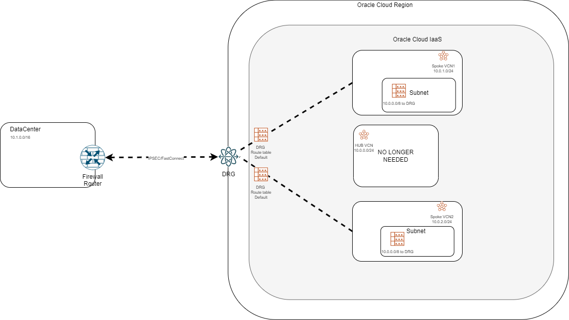
There are many reasons to choose the new design over the old one but the most important one would be that it provides a lot more options for complex architectures.
For a detailed deployment procedure for each architecture, please check this blog: Hub-and-spoke
For more details on the capabilities of the Enhanced DRG, please check this blog: Enhanced DRG
But can we migrate easily from the old design to the new one? Can it be done without interrupting traffic? The answer is “yes” to both questions. Let’s look at a small migration procedure in the lab below.
2. Lab
Before we start we need to understand that this works only with the Enhanced DRG. So the first thing we need to do is to upgrade the DRG if it is the older version. To check the DRG version go to the DRG overview menu and check for this message at the top of the page:

If you see that message then you are on the old DRG version and you need to upgrade before moving on.
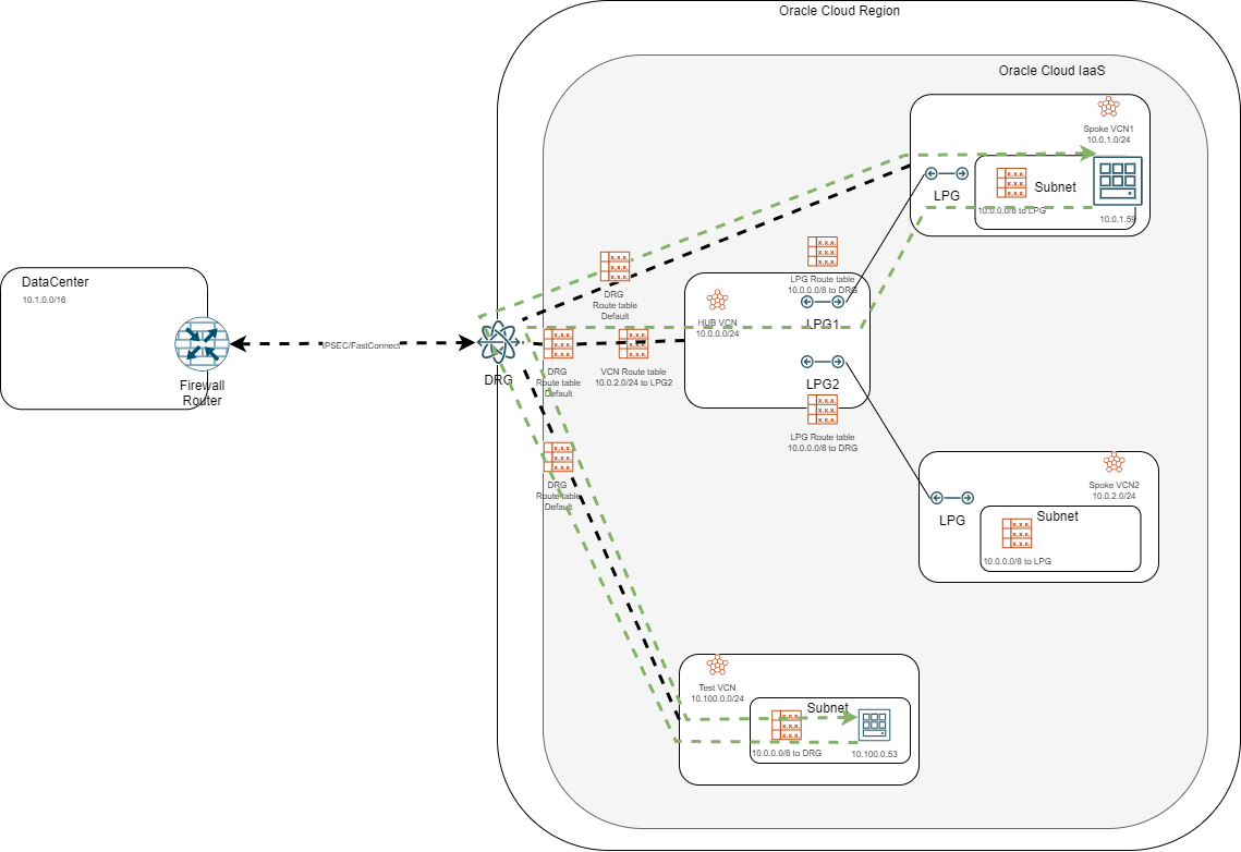
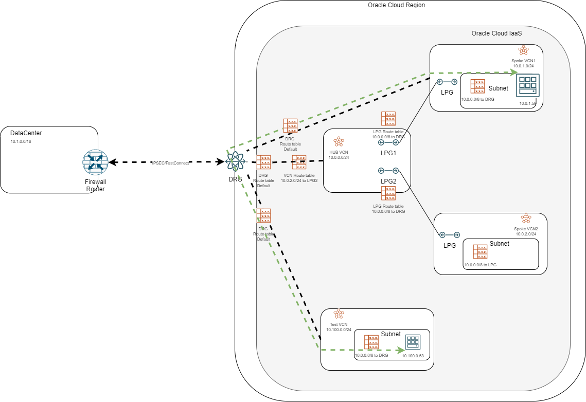
This is the starting architecture:
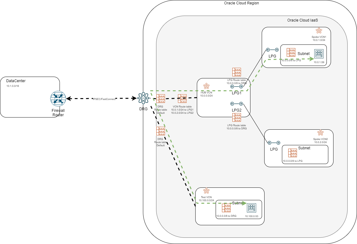
We have the hub-and-spoke design using LPGs and we also have a Test VCN attached to the DRG which we will use to test traffic interruption. Before doing any change I started a continuous ping from the bottom Compute instance (10.100.0.53) to the instance in Spoke 1 (10.0.1.59).
When we attach a VCN to the DRG we can put two route tables on that attachment:
a) A DRG route table – this is mandatory and it allows the DRG to learn which CIDRs are inside the attached VCN
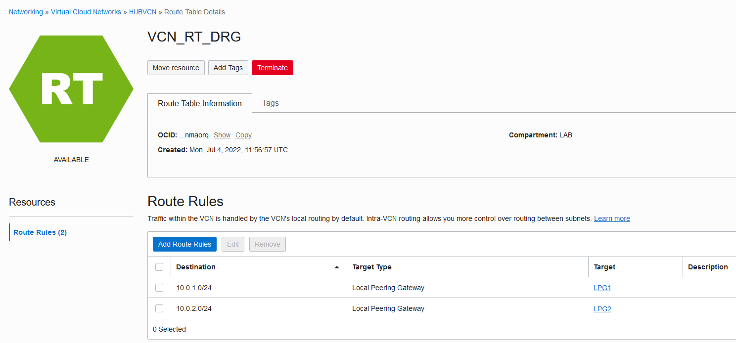
b) A VCN route table – this is optional and it allows the DRG to learn which VCN CIDRs are connected to the current VCN via LPGs; in our case, the VCN Route Table looks like this:
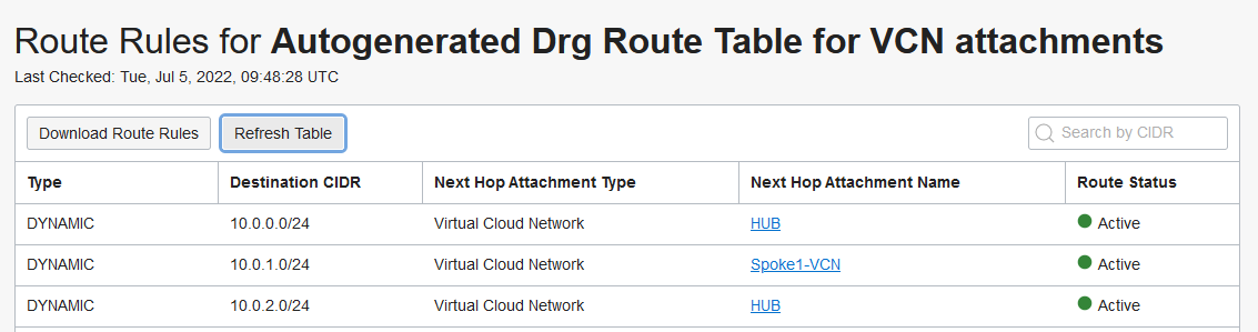
Next, let’s check how the Test VCN knows how to reach the Spoke1 VCN CIDR. We can look at the DRG route table of the TEST VCN, where we will click “Get all routes”:
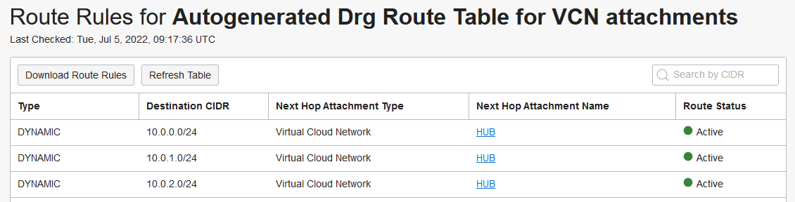
So the Test VCN DRG route table learns the following CIDRs are reachable via the HUB VCN:
- 10.0.0.0/24 – the HUB VCN CIDR
- 10.0.1.0/24 – the Spoke 1 VCN CIDR
- 10.0.2.0/24 – the Spoke 2 VCN CIDR
Now let’s migrate this design to the DRG hub-and-spoke model:
i. The first step is to attach the SPOKE1 VCN to the DRG directly, which will make the architecture look like below:
Go to the DRG VCN attachments and a new one:
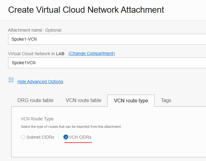
Make sure you are going to “advanced options” and you are selecting VCN CIDRs in the VCN Route Type menu. Create the attachment.
After Spoke1 is attached to the DRG, the Test VCN will learn that it can reach the Spoke CIDRs directly:
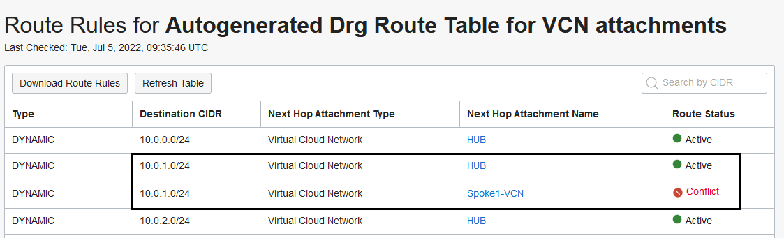
However, because the CIDR was already advertised by the HUB VCN, the new route will be marked as a “conflict” and it will be used as a backup of the existing route through the HUB.
ii) The second step is to stop the HUB from advertising the Spoke CIDR.
Go to the VCN route table attached to the DRG VCN attachment and remove the line pointing the Spoke CIDR to the Spoke LPG:
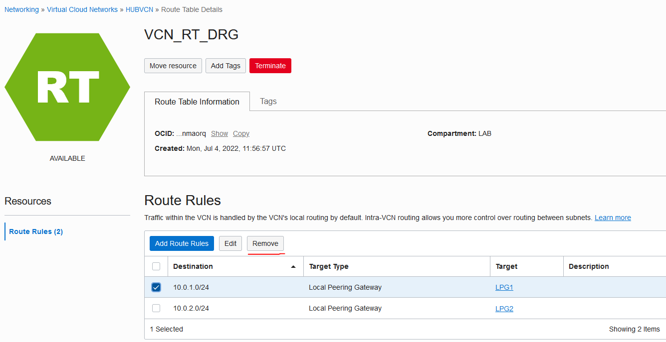
The moment you remove the HUB VCN will stop advertising the SPOKE CIDR:
If the HUB VCN DRG attachment no longer advertised the SPOKE1 CIDR then the direct route will become Active (it was previously marked as Conflict).
At this point the routing becomes asymmetric because traffic towards the Spoke1 VCN will use the direct attachment in the DRG while return traffic will still use the LPG, as shown below:
iii) The last step is to go into EACH used VCN Route table inside the Spoke VCN and edit the routes targeting the LPG by retargeting them to the DRG.
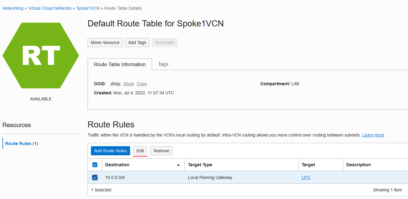
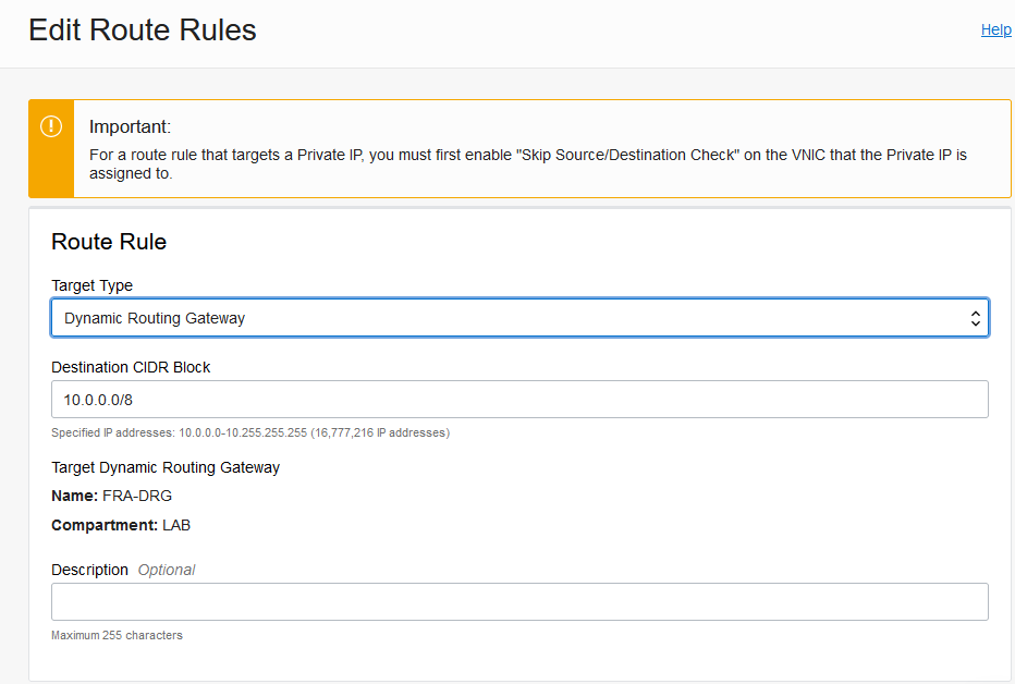
After this step the routing becomes symmetric again, as shown below:
Important note: if you have services deployed in the HUB VCN you will need to route from the HUB VCN to the SPOKE VCN via the DRG instead of the LPG.
iv) The final step is allocated to cleanup.
- Delete the LPG dedicated to Spoke 1 from the HUB
- Delete the LPG dedicated to the HUB from the Spoke1 VCN
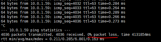
And this is it, we migrated Spoke 1 from LPG connectivity to direct connectivity in the DRG. Now repeat the same process for any other Spoke. During the implementation of the steps above the continuous ping never lost packets:
3. Conclusion
It is possible to migrate from the LPG architecture without impact to traffic. With the new DRG features you open the door to more complex architectures that will greatly improve your cloud experience and allow you to better fulfill the business requirements.
Note: This procedure was done on a simple deployment where many constructs were on the default settings. If you have an existing complex LPG design with advanced configuration you may need to take extra steps to ensure a smooth migration. Even though the steps presented showed no traffic loss please do these changes in a change window as your custom design may behave differently.
