Overview
This documents provides a guide how to deploy Palo Alto (PA) VM-Series firewalls in High Availability (HA) Mode within OCI. Palo Alto will monitor the interfaces of the PAs or can also monitor a path and when an issue is detected it triggers a call to Oracle Cloud Infrastructure (OCI) to move the Virtual IPs (VIP) between the two PAs using OCI instance principles.
Implementation
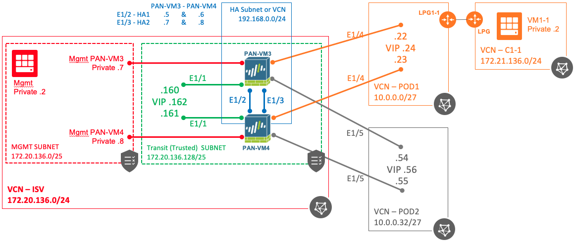
The diagram below represents the environment used for this test. In the diagram solid lines represent a VCN while the dotted line represents a subnet within the VCN. VCNs without the subnets depicted means it has a single subnet of the same size as the VCN. Note the color codding to depict to what subnet or VCN a particular interfaces is connected to.
Couple things to note in the diagram:
- The first VNIC created when a VM is instantiated if part of the management subnet (red) and it becomes the management interface for the PA. This interface will interact with OCI API to move the VIP from one VM to the other. This interface needs Internet access.
- The trust interface is on the transit subnet (green) and is on the trust security zone
- The requirement is that the HA interfaces are on different subnets than data interfaces (trust and untrust interfaces). The HA interfaces could be on the ISV VCN if it had a third subnet but unfortunately in this exercise it does not. For this reason the HA interfaces in this exercise are in a different VCN (blue) but it is NOT a requirement.
- Untrust interfaces are connected to different VCNs (POD1 orange and POD2 gray). They are on their own security zone. POD1 and POD2 security zone respectively
- Traffic from POD1 to VCN C1-1 is done via a Local Peering Gateway (LPG)
- VIPs or secondary IP addresses are only created for the data interfaces and they are only created on PAN-VM3 (primary)
Also check the blog for Hub and Spoke design
Palo Alto VM-Series Firewall
Palo Alto also has step-by-step documentation how to deploy their VM-Series Firewall in OCI. Please review this documentation for additional information. This document will provide links to those guides and will update or add additional information to the steps and some new ones.
Before You Start
- You need Palo Alto 9.1 code version or higher
- Consider the shape of the VM to use. The shape should be selected based on the number of interfaces (VNICs) that you need. The minimum number of VNICs required for an HA deployment is 4 (Mgmt, H2, Trust, and Untrust) if you use the management in terface for HA1 as well. If do want to follow this approach then the minimum is 5 interfaces (Mgmt, HA1, HA2, Trust, and untrust). In the example on this document each VM has 6 VNICs (Managment, HA1, HA2, Trust, 2xPODs) per diagram above
- Licensing – You need the proper license from Palo Alto to support the bandwidth and the number of VNICs required for your solution
- When deploying the VMs, make sure the initial VNIC for your VM is on your management subnet as Palo Alto will use the first interface in the VM as the management interface
- You need a Palo Alto support account in order to download the VM-series image or go through Oracle Market Place
Launch the VM-Series Firewall in OCI
Follow the instructions provided by Palo Alto. Below are some comments which complement the instructions provided by Palo Alto
- STEP 1 – Proceed as stated
- STEP 2 – Proceed as stated
- STEP 3 – Proceed as stated
- STEP 4 – Make sure the VMs in the cluster are created in different ADs for redundancy
- STEP 5 – Proceed as stated
- STEP 6 – Select the proper shape based on the number of interfaces required and the throughput. Remember to count the management interface (default) as an additional interface on top of the other interfaces required
- STEP 7 – The default VNIC when you create the VM should be on your management subnet. Make sure you select the proper subnet. This interface will become your management interface for the PA. You will use it to manage the firewall and access it through the GUI. Also this interface is used to make API calls to move the VIP from one VM to the other. It requires Internet access.
- Make sure you Check Assign a public IP address if you are planning to manage it over the Internet
- STEP 8 – Proceed as stated
- STEP 9 – Proceed as stated
- STEP 10 – Check the additional information from Palo Alto. The Panorama-related fields are required only if you have a Panorama appliance and want to use Panorama to manage your VM-Series firewall.
- hostname=<fw-hostname>
- authocodes=<firewall-authcode>
- op-command-modes=jumbo-frame
For Panorama
- vm-auth-key=<auth-key>
- panorama-server=<panorama-ip>
- panorama-server-2=<panorama2-ip>
- tplname=<template-stack-name>
- dgname=<device-group-name>
- STEP 11 – Proceed as stated
- STEP 12 – Proceed as stated
- STEP 13 – On this step you will create the additional interfaces required for the HA cluster. As mentioned before for this exercise it needs 6 VNICs total ((Management, HA1, HA2, Trust, 2xPODs). Create the VNICs in the same order on both VMs because you will need to associate them at a later step from the Palo Alto GUI (assign IPs, name, security zones, etc.)
- Management
- Already created in step 7 as it is the default VNIC when the VM is created – You can update the interface name if needed
- Control Link HA1 & DataLink HA2 – These interfaces are used to setup the HA cluster
- Create two VNICs one called HA1 and the other HA2
- Make sure to UNCHECK the box Skip Source/Destination Check
- Assigned the IP address to each interface per you design
- Trust
- Make sure to CHECK the box Skip Source/Destination Check – This is required because when you create a route rule pointing to this interface will generate an error on the Oracle Console if this option is not checked.
- Note: If the VCNs where you are creating the trust interface is on different compartment you will need to have access to that compartment.
- Enter the primary IP address per your design.
- Add the VIP IP address as a secondary IP address for the Trust interface. This is the VIP IP address that will move between the two VMs in the cluster. You only need to add the VIP to one of the VMs in the cluster
- Make sure to CHECK the box Skip Source/Destination Check – This is required because when you create a route rule pointing to this interface will generate an error on the Oracle Console if this option is not checked.
- Untrusted
- Create an untrusted interface for each untrusted segment on your design. For this example one interface for each POD named POD1 and POD2
- Note: If the VCNs where you are creating the additional interfaces are on different compartments you will need to have access to that compartment.
- Make sure to CHECK the box Skip Source/Destination Check – This is required because when you create a route rule pointing to this interface will generate an error on the Oracle Console if this option is not checked.
- Add the VIP IP address as a secondary IP address for each untrust interface. This is the VIP IP address that will move between the two VMs in the cluster. You only need to add the VIP to one of the VMs in the cluster
- Reboot the VMs
- Create an untrusted interface for each untrusted segment on your design. For this example one interface for each POD named POD1 and POD2
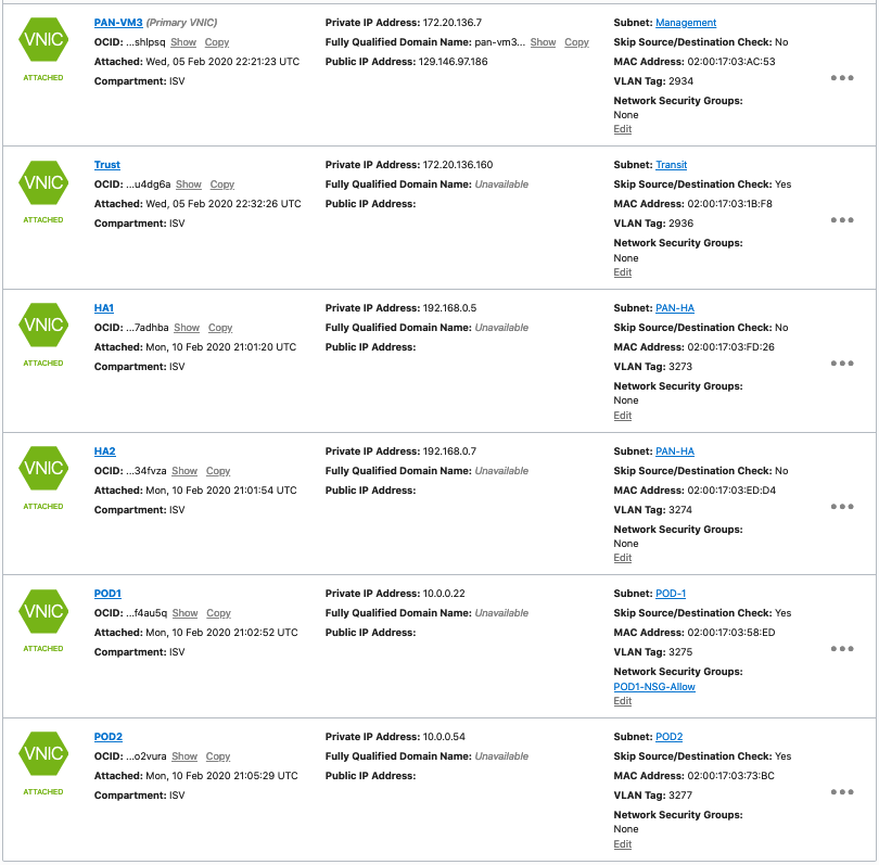
- This is how your VM should look like after creating all the VNICs
- Management
- NEW STEP13a – Repeat steps 1-13 for the second VM. Remember not to add the secondary IP addresses on the second VM
| PAN-VM3 |
 |
| PAN-VM4 |
 |
- STEP 14 – This step configures the PA interfaces from the PA GUI
- You need to match the interfaces created in the Oracle Console with Interfaces on the PA. You need to use the same order starting from the second VNIC you created in the Oracle Console matching to ethernet1/1 on the PA GUI. Do not need to add the primary VNIC as that is the management interface
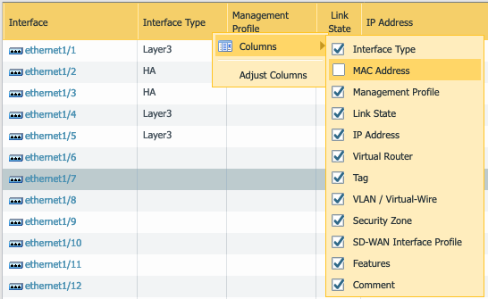
- Add the MAC Address column on the Interfaces screen so you can match the correct interface with the Oracle Console screen as shown in step 10a above. Click the arrow by the Interface column, select columns, and check MAC Address
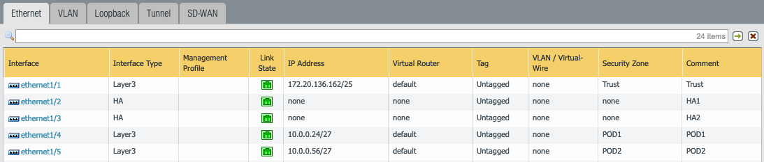
- When adding the IP address to the PA interfaces, do NOT enter the primary IP address of the interface, only add the SECONDARY IPs assigned to the VNICs in the Oracle Console. Also add the corresponding subnet mask as you did when creating them on the Oracle Console. For example for the trust interface on PAN-VM3 the primary IP address is 172.32.136.160 and the secondary is 172.32.136.162. Only add 172.32.136.162 to ethernet1/1.
- Do not add IPs for the HA interfaces as they are assigned at a later time during the HA configuration
- Do not forget to add the mask to the IP address of the interface
- Table below shows the corresponding configuration in the Oracle Console and the configuration on the PA GUI. The text shows the IPs assigned to each interface in the Oracle console for each VNIC. The PA GUI shows the secondary IP address assigned to the VNIC. No need to configure the interfaces on the second PA because when the HA configuration is complete the configuration will sync between the two VMs.
| PAN-VM | Oracle Console | PA Console Interface |
| 3 | Management – 172.20.136.7/25
Trust – Primary 172.20.136.160/25 Secondary 172.20.136.162/25 HA1 – 192.168.0.5/25 HA2 – 192.168.0.7/25 POD1 – Primary 10.0.0.22/27 Secondary 10.0.0.24/27 POD2 – Primary 10.0.0.54/27 Secondary 10.0.0.56/27 |
ethernet1/1- 172.20.136.162/25
ethernet1/2 ethernet1/3 ethernet1/4 – 10.0.0.24/27
ethernet1/5 – 10.0.0.56/27 |
| 4 | Management – 172.20.136.8/25 Trust – Primary 172.20.136.161/25 HA1 – 192.168.0.6/25 HA2 – 192.168.0.8/25 POD1 – Primary 10.0.0.23/27 POD2 – Primary 10.0.0.55/27 |
Configuring the PAs in a Cluster for HA
Follow the instructions below to configure both PAN-VM3 and PAN-VM4 or use the documentation for HA on OCI from Palo Alto
- STEP 1 – Connect to the PAN-VM3 GUI via the browser using its public IP address or private if you have a path to it. Perform the same step for PAN-VM4
- PAN-VM3 – https://x.x.x.x/php/login.php?
- PAN-VM4 – https://y.y.y.y/php/login.php?
- If you can’t HTTPS to it, check the security list on the management subnet in the Oracle Console to see if HTTPS traffic is allowed
- STEP 2 – Select the device tab, select the High Availability section on the left menu, and select the General tab, the right pane has 7 sections
- STEP 3 – Click the gear icon for the Setup section
- Check Enable HA, give a group ID number, select mode Active-Passive (Active-Active is not supported), check Enable Config Sync, enter the IP address of the Peer HA1 IP address. When configuring PAN-VM3, this is the IP address of the HA1 interface on PAN-VM4 (192.168.0.6). When configuring PAN-VM4, this is the IP address of the HA1 interface on PAN-VM3(192.168.0.5)
- Click OK
- STEP 4 – Click the gear icon for the Active/Passive Settings section
- Check Shutdown
- Click OK
- STEP 5 – Click the gear icon for Election Settings section
- Device Priority – PAN-VM3 = 100 and PAN-VM4 = 110
- Preemptive – This is optional and it depends if you want the traffic to failback to the primary PAN-VM when it is restored after a failure or not
- Note that the HA Timer Settings (Recommended is 60s). So preempt will take 60s to fallback after the primary PAN-VM is restored
- Click OK
- STEP 6 – Click the gear icon for Control Link (HA1) section
- Select the Interface for HA1 (see the picture on STEP 16 above) ethernet1/2
- Enter the IP address for PAN-VM3 and PAN-VM4 respectively for the interface, enter the subnet mask, gateway is not required if the PAN-VMs are in the same subnet
- Click OK
- STEP 7 – Click the gear icon for Data Link (HA2) section
- Check Enable Session Synchronization
- Select the interface for HA2 (see the picture on STEP 16 above) ethernet1/3
- Enter the IP address for PAN-VM3 and PAN-VM4 respectively for the interface, enter the subnet mask, gateway is not required if the PAN-VMs are in the same subnet
- Change the Transport to UDP
- Click OK
- STEP 8 – Your HA configuration should look like this for your PAN-VMs
| PAN-VM3 |
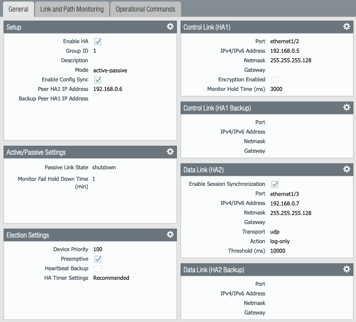 |
| PAN-VM4 |
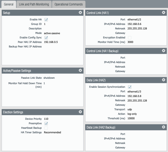 |
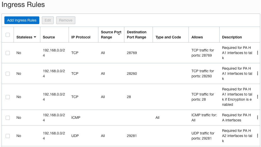
- STEP 9 – For the HA interfaces to talk and exchange information make sure the security list associated with the subnet where the HA interfaces reside have the proper ports opened. HA1 requires TCP port 28769 and 28260 and ICMP. If you enable encryption on HA1 you also need TCP port 28. HA2 requires UDP port 29281
- STEPS 10-12 are optional. If you want to setup path monitoring which will check if some destination host is reachable via any of the interfaces as a condition for HA, proceed to implement them. Perform the same configuration on both PAN-VMs
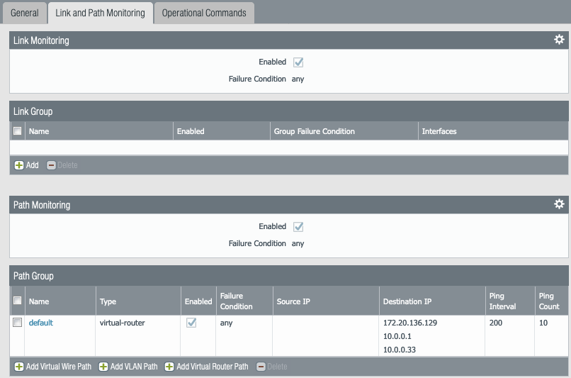
- STEP 10 – Click the Link and Path Monitoring Tab, the right pane has 4 sections
- STEP 11 – On the Path Group section, click on Add Virtual Router Path (3rd option). Do not click Add Virtual Wire Path
- Select the default name or give it a new name
- For the purpose of this exercise we are going to monitor the default gateway for each data interface
- Under destination IP, add the default gateway for each of the VNICs for example (Trust (172.20.136.129), POD1 (10.0.0.1), POD2 (10.0.0.33)) which is the first IP address of the subnet. You can use a destination IP that you want to monitor
- This is used to check a path going beyond of just checking the physical interfaces of the cluster and failover to the standby PA if the destination is not reachable
- Click OK
- STEP 12 – Your Link and Path Monitoring should look like this
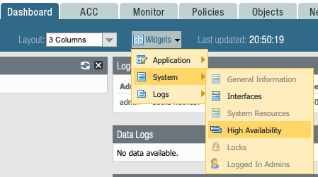
- STEP 13 – Select the Dashboard tab
- Click on the Widgets pull down menu on top
- Select System, select High Availability, this will give you a good view of the state of HA in your dashboard
- You can re-arrange the widgets to your preference
- The first time you configure HA you will have to manually sync the configs between the two VMs, click the Sync Config link next to the Running Config section
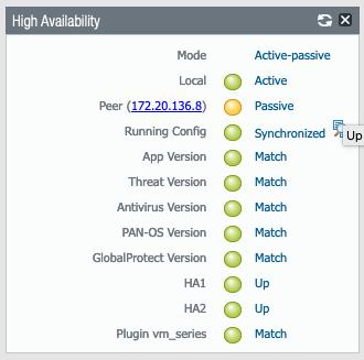
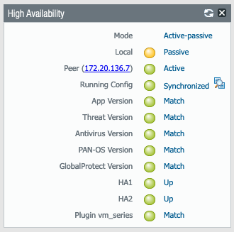
- Under the High Availability widget you can see Running Config sync status between your PAN-VMs. You can also see which is Active and Passive.
- STEP 14 – Click Commit button
- Once the PAs sync and if HA is configured properly you should see the status like this
- Proceed to the next section to configure instance principles in the OCI Console
| PAN-VM3 | PAN-VM4 |
 |
 |
OCI Instance Principles
On the previous steps you configured the PAs and set them up to work in a cluster for HA. The next step is to configure OCI to work in conjunction with the PAs to move the VIP from one VM to the other when PA detects an issue. PA interacts with OCI APIs and uses instance principles to move the VIP. The PAs use the management interface to make call the API and it needs Internet access. First you need to create a Dynamic Group wich contains the two VMs in the cluster and second you will create a policy to allow the Dynamic Group to move the VIP IP from one VM to the other. To configure instance principles, perform the following steps:
- STEP 1 – Log into the Oracle Console
- STEP 2 – Collect OCIDs for the PAN-VMs
- Select Compute from the main menu and select instances
- Copy the OCID for the two PAN-VMs
- PAN-VM3 OCID – ocid1.instance.oc1.phx……………………………..xlcsw6a
- PAN-VM4 OCID – ocid1.instance.oc1.phx…………………………….gp7xe2q
- STEP 3 – Create Dynamic Groups
- Select Identity from the hamburger menu and select Dynamic Groups
- Add the PAN-VMs into the Dynamic Group
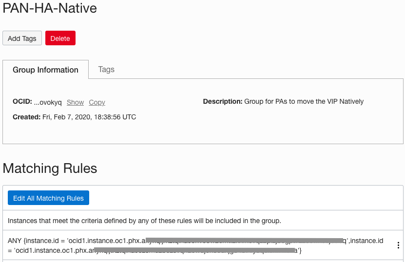
- Click Create Dynamic Group
- Give it a name PAN-HA-Native for example
- Under Matching rules enter the rules below, use the OCID collected in STEP 2
- Click Create Dynamic Group
| Name – PAN-HA-Native |
| Matching rules ANY {instance.id = ‘OCID for PAN-VM3′,instance.id = ‘OCID for PAN-VM4′} |
 |
Note: If the VCNs you are connecting with the different interfaces in your firewall are in different compartments, then you need to create the policy below for each compartment to grant the Dynamic Group created above the access on that compartment, otherwise the secondary IP address will not move to the passive firewall. Without creating the policies in the other compartment you will see that perhaps only one or some secondary IPs move but not all.
- STEP 4 – Create a Policy
- Select Identity from the hamburger menu and select Policies
- Click Create Policy
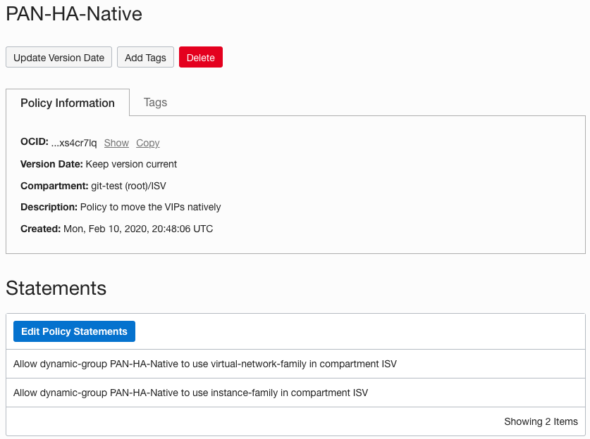
- Give it a name PAN-HA-Native
- Under Policy Statements type the statements below, one per statement. Click the + sign to add another line for the second statement
- In the statement below replace <your compartment> with the compartment where the PAN-VMs are located
- Click Create
| Name – PAN-HA-Native |
| Statements Allow dynamic-group PAN-HA-Native to use virtual-network-family in compartment <your compartment> Allow dynamic-group PAN-HA-Native to use instance-family in compartment <your compartment> |
 |
At this point you are done with the configuration of the environment. The next step is to test your HA configuration.
PA Routing, Policy, Licensing Configuration
On this section you will add routes or networks the PA is not directly connected to. In the following steps you will add static routes to PAN-VM3 only; as they are already configured on a HA cluster, configuration will be replicated to PAN-VM4. You will also configure the policies between the different security zones based on your security requirements. You will also add the proper license in order for the PAs to be fully functional.
- STEP 1 – Log into PAN-VM GUI interface
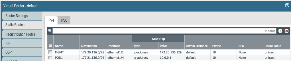
- STEP 2 – Select Network tab, select Virtual Routers, select the profile you used previously
- STEP 3 – Select the Static Routes tab, click add.
- Name – Enter the name for the route, for example customer name
- Destination – Enter the customer VCN subnet with mask
- Interface – Select the proper interface to reach that customer
- Next Hop – Select IP address and in the field below enter the IP address of the next hop
- Click OK
- Add a route for each of the subnets you need connectivity to
- Your route table should look like this when done
- Click OK when done
- STEP 4 – Commit changes
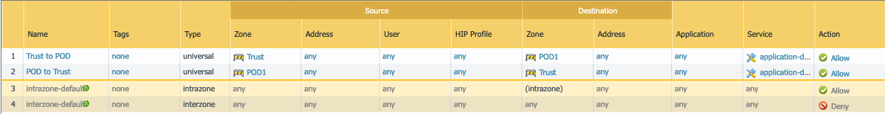
- STEP 5 – Select the Policies tab, click the Add button on the bottom left side
- Add the necessary policies based on your requirements to allow traffic between the different security zones
- Allow traffic in the direction of who initiate the flow, the policies are stateful so there is no need to open traffic for the return traffic
- If traffic is to be initiated from the opposite direction then you need to configure the proper policy
- For the purpose of this test I have the policies wide open as you can see below
- STEP 6 – Commit changes
- STEP 7 – Select the Dashboard tab, make sure the configuration in synced between your PAN-VMs
- STEP 8 – Select the Device tab, select Licenses on the left list (almost at the bottom)
- STEP 9 – Under License Management box (last section on the right side), select the proper way to add the license to your PAN-VMs
- You have to do this step on each PAN-VM
Jumbo Frames
By default the MTU size on the interfaces is set to 1500. To change it to 9000 follow these steps:
- STEP 1 – Select the Device tab, select Setup from the left list
- STEP 2 – Select the Session tab
- STEP 3 – Click the gear icon under Session Settings section
- Check the box for Enable Jumbo Frame
- Click OK. You will get this message “Enabling/disabling Jumbo Frame mode requires a device reboot. L3 interfaces will inherit the Global MTU value unless it has been configured explicitly with its own MTU. Do you want to continue?”
- Click OK
- STEP 4 – To change at the interface level, is not required as it will inherit the configuration from the Global MTU set in STEP 3. If you would like to set it up, select the Network tab, select Interfaces from the left list
- STEP 5 – Select an interface
- Click Advance tab
- Update the MTU field to 9192
- Click OK
- Repeat STEP 5 for all the interfaces you want to use Jumbo Frames
- STEP 6 – Commit changes
How to Test HA Functionality
Unfortunately there is no way to test the HA functionality by shutting the PA interfaces as you do not have access to the OS on the PAN-VM. Because the HA is Active/Passive if you shut down an interface from the PA GUI or console and commit the change, it will replicate to the passive PA. You can use the GUI to failover manually from one PA to the other but not to mimic a failover scenario. Below are some ways to test the functionality. The third option test Path Monitoring only.
When you perform failover test check that the PAs status move from active to passive and passive to active respectively. Also log into the Oracle Console, select Compute from the hamburger menu, select Instances and select PAN-VM3 or PAN-VM4. When HA moves from PAN-VM3 to PAN-VM4 you should see in the Oracle Console how the secondary IP address for Trust and the two untrust interfaces (POD1 and POD2) move from PAN-VM3 to PAN-VM4. This will confirm that your configuration is done correctly.
From the CLI
- Use the console connection and credentials you created on STEP 12 on section Launch the VM-Series Firewall in OCI
- Log as admin and enter the password
- You can run the following command on the active PA to check if passive is able to take over:
- request high-availability state suspend
- On the other hand, if you want to suspend the passive node from the active PA, you use the following command
- request high-availability state peer suspend
- Once you suspend either of the nodes, to bring them back to the normal operational state you have to run the following command:
- request high-availability state functional
- Use the command below to check the state of HA
- show high-availability state
- show high-availability all
From the GUI
- Go the Device Tab, select High Availability on the left list, and select Operational Commands tab
- You can suspend local device
- Also you can Select Setup from the left list, and select the Operations tab, under Device Operations section
- You can Reboot Device
- You can Shutdown Device
- On the Dashboard tab you can check which one is active and passive
Network Security Groups
To mimic an interface no able to reach its default gateway which will trigger the path monitoring process if configured you can follow these steps for testing purposes. WARNING this can be done on a POC environment, but NOT recommended for production.
This example is performed on VNIC POD1
- STEP 1 – Log into the Oracle Console, select Networking from the hamburger menu, select Virtual Cloud Networks
- STEP 2 – Select POD-1 VCN
- Select the POD-1 subnet
- Select the security list associated with this subnet – This can be done if this is not a production environment
- Write down the Ingress rules and Egress rules, do a screen capture or write them down somewhere to rebuild it when done
- Remove all the Ingress and Egress rules
- Go back to the POD-1 VCN
- STEP 3 – Select Network Security Groups (NSG) from the Resources list on the leftClick Create Network Security Group
- You will create two NSGs
- Create NSG called POD1-NSG-Allow
- For testing purposes create an Ingress rule to allow all the traffic for all the protocols
- Create a similar rule for an Egress rule
- Create NSG called POD1-NSG-Deny
- Do not add any rules, it will be an empty NSG which basically will deny any traffic
- STEP 4 – From the main menu, select Compute, select Instances
- Select the PAN-VM3
- Select Attached VNICs from the Resources list on the left
- On the POD1 VNIC, on the right side under Network Security Groups, it should say None with an Edit button below
- Click the Edit button
- Select the proper compartment
- Select the POD1-NSG-Allow Network Security Group
- Save Changes
- Select the PAN-VM4 instance and repeat the steps above
- STEP 5 – Once this is done check the HA status on both PAN-VMs
- PAM-VM3 should be Active and PAN-VM4 should be Passive
- STEP 6 – Now to mimic a failover, we are going to block all the traffic on the POD1 interface on PAN-VM3 and this will trigger the path failover process to make PAN-VM4 the active PA
- Select the PAN-VM3
- Select Attached VNICs from the Resources list on the left
- On the POD1 VNIC, on the right side under Network Security Groups, click the Edit button
- Select the POD1-NSG-Deny Network Security Group
- Save Changes
- This will block all the traffic from POD1 interface on PAN-VM3 only making the path monitor to fail and for the HA process to trigger to move the services to PAN-VM4 and change status from Passive to Active
- STEP 7 – Check the PA GUI for both PAs and see the HA status
- By changing the NSG on the POD1 interface you can mimic a failover.
- You can change the NSG back to POD1-NSG-Allow on PAN-VM3 to bring everything back to normal.
- Once you are done you can remove the NSGs and update the security list with the rules you backed up in a previous step
HA Tests
For test purposes I have a ping test running from Mgmt VM (172.20.136.2) to a VM (VM1-1 172.21.136.2) out of POD1 VCN.
Test 1 – Active to Passive and Passive to Active
Initial state PAN-VM3 (Active), PAN-VM4 (Passive)
- If PAN-VM4 (Passive) is suspended
- Nothing happens, no packet loss. PAN-VM4 becomes suspended, no IPs moved, PAN-VM3 is still active
- If PAN-VM4 (Passive) is functional
- Nothing happens, no packet loss. PAN-VM4 becomes passive no IPs moved, PAN-VM3 is still active
- If PAN-VM3 (Active) is suspended
- Lost 11-14 packets while IPs (3) are moved. PAN-VM3 becomes suspended and PAN-VM4 becomes active
- 64 bytes from 172.21.136.2: icmp_seq=738 ttl=63 time=1.90 ms
- 64 bytes from 172.21.136.2: icmp_seq=739 ttl=63 time=1.92 ms
- 64 bytes from 172.21.136.2: icmp_seq=740 ttl=63 time=1.85 ms
- 64 bytes from 172.21.136.2: icmp_seq=754 ttl=63 time=0.844 ms
- 64 bytes from 172.21.136.2: icmp_seq=755 ttl=63 time=0.850 ms
- 64 bytes from 172.21.136.2: icmp_seq=756 ttl=63 time=0.784 ms
- If PAN-VM3 (Suspended) is functional
- PAN-VM3 becomes passive, no packet loss, no IPs moved, PAN-VM4 is still active. If preempt configured then PAN-VM3 will become active after the preempt time expires (about 60s). 10-12 packets are lost and the IPs (3) are moved.
- If preempt is not configured PAN-VM4 (Active) is suspended
- Lost 11-17 packets while IPs (3) are moved. PAN-VM4 becomes suspended and PAN-VM3 becomes active
- 64 bytes from 172.21.136.2: icmp_seq=834 ttl=63 time=0.782 ms
- 64 bytes from 172.21.136.2: icmp_seq=835 ttl=63 time=0.777 ms
- 64 bytes from 172.21.136.2: icmp_seq=836 ttl=63 time=1.02 ms
- 64 bytes from 172.21.136.2: icmp_seq=853 ttl=63 time=1.96 ms
- 64 bytes from 172.21.136.2: icmp_seq=854 ttl=63 time=1.95 ms
- 64 bytes from 172.21.136.2: icmp_seq=855 ttl=63 time=1.92 ms
Test 2 – Reboot Active PAN-VM
- Initial states PAN-VM3 (Active), PAN-VM4 (Passive)
- If PAN-VM3 (active) is rebooted
- Lost 11-14 packets while IPs (3) are moved. PAN-VM3 is rebooted and PAN-VM4 becomes active. When PAN-VM3 is up it is passive and PAN-VM4 is still active. If preempt configured then PAN-VM3 will become active after the preempt time expires (about 60s). 10-12 packets are lost and the IPs (3) are moved.
- 64 bytes from 172.21.136.2: icmp_seq=1514 ttl=63 time=1.97 ms
- 64 bytes from 172.21.136.2: icmp_seq=1515 ttl=63 time=1.88 ms
- 64 bytes from 172.21.136.2: icmp_seq=1516 ttl=63 time=1.84 ms
- 64 bytes from 172.21.136.2: icmp_seq=1530 ttl=63 time=1.01 ms
- 64 bytes from 172.21.136.2: icmp_seq=1531 ttl=63 time=0.912 ms
- 64 bytes from 172.21.136.2: icmp_seq=1532 ttl=63 time=1.01 ms
Test 3 – Path Monitoring
- Initial states PAN-VM3 (Active), PAN-VM4 (Passive)
- Disable PAN-VM3 (active) path to default gateway 10.0.0.1 for POD1 interface
- Lost 11-12 packets while IPs (3) are moved. PAN-VM3 becomes Non-functional (Path down) and PAN-VM4 becomes active. It takes maybe 20s or so to detect the path down.
- 64 bytes from 172.21.136.2: icmp_seq=387 ttl=63 time=1.98 ms
- 64 bytes from 172.21.136.2: icmp_seq=388 ttl=63 time=1.95 ms
- 64 bytes from 172.21.136.2: icmp_seq=389 ttl=63 time=1.90 ms
- 64 bytes from 172.21.136.2: icmp_seq=400 ttl=63 time=2.00 ms
- 64 bytes from 172.21.136.2: icmp_seq=401 ttl=63 time=1.83 ms
- 64 bytes from 172.21.136.2: icmp_seq=402 ttl=63 time=1.93 ms
- Enable PAN-VM3 (active) path to default gateway 10.0.0.1 for POD1 interface
- PAN-VM3 becomes passive and PAN-VM4 is still the active. If preempt configured PAN-VM3 becomes active and PAN-VM4 becomes passive. Lost 11-13 packets while IPs (3) are moved.
- 64 bytes from 172.21.136.2: icmp_seq=779 ttl=63 time=0.855 ms
- 64 bytes from 172.21.136.2: icmp_seq=780 ttl=63 time=1.00 ms
- 64 bytes from 172.21.136.2: icmp_seq=781 ttl=63 time=0.959 ms
- 64 bytes from 172.21.136.2: icmp_seq=794 ttl=63 time=1.96 ms
- 64 bytes from 172.21.136.2: icmp_seq=795 ttl=63 time=2.00 ms
- 64 bytes from 172.21.136.2: icmp_seq=796 ttl=63 time=2.04 ms
HA Troubleshooting
If your HA configuration is not working properly check the following items to make sure your configuration is correct
- Check the MAC address of the VNIC create in Oracle Console to match with the correct interface configured in Palo Alto interface configuration. If they do not match you will not be able to ping from the firewall devices in the VCN or segment where the interface is connected to
- HA interfaces should be on different subnets than the management and data interfaces. If HA is on the same subnet as one of the other interfaces, the secondary IP addresses will not move to the passive firewall during a failover
- Is the session and config sync successful? If not, maybe HA config is not correct. Check both firewalls to make sure the HA configuration is done correctly
- If the management interface is being used as HA1, you will explicitly have to add DNS server IP (and OCI DNS 254.169.254.169 has to be primary). Otherwise the API calls won’t be able to resolve the API endpoint IP
- Management interface does not have access to the Internet. Without access to the Internet the management interface will not be able to reach the API server to move IPs
- If the he FW interfaces are in different compartments than the firewalls themselves, then a policy should be created under each compartment to give the dynamic group access to that compartment and allow the API to move the secondary IPs. Otherwise only some IPs will move and not all
- From CLI try mp-log pan_vm_plugin.log to see if the log shows any reasons why the failover is not working
Check other blogs from Javier Ramirez