Introduction
This blog post is a continuation of the previous Part 1 post where the necessary steps for the OCI Network were done. This post will show the steps involved in deploying a BIG-IP VE on the Oracle Cloud Infrastructure. The configuration steps for the BIG-IP VE will be discussed in Part 3 of this series.
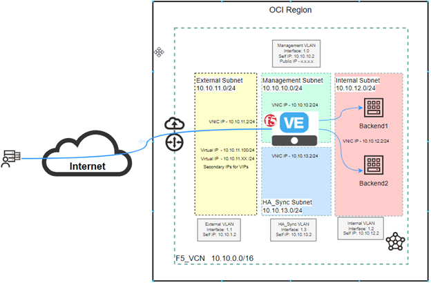
Topology Diagram for reference
Deploying BIG-IP VE
As of this writing, the F5 BIG-IP VE image is not available in the Oracle Marketplace, and hence to install the BIG-IP VE image, it will need to be downloaded from the F5 Downloads page and then a custom image will need to be created on the Oracle Cloud Infrastructure. Once the custom image is created then the VE can be deployed with that image and the right shape in to get the right number of CPUs, Memory, and vNICs.
Download a BIG-IP VE image
- Visit the F5 Downloads page and log in with your account.
- Click Find a Download and then under the Product Line click the version you want.
- Under Name, click x.x.x.x_Virtual-Edition, where x.x.x.x is the product container you want to download, and then at the license agreement notification click, I Accept.
In this example, we have chosen version 17.0.0-0.0.22.
- Under Filename, click one of the qcow2.zip image files and then download.
- Once downloaded, unzip the .qcow2 file.
Create a Storage bucket for Image Upload
This sub-task will contain the steps to create a storage bucket, and then upload the .qcow2 image from the previous step.
- In the OCI console, under the Home menu, click Object Storage. Ensure you are in the right compartment and then click Create Bucket.
- Provide a Name for the bucket and then Click Create Bucket leaving all other settings at default.
- Once the bucket is created Click on the newly created bucket and then on the left menu click on Pre-Authenticated Requests and then click Create Pre-Authenticated Requests to create one.
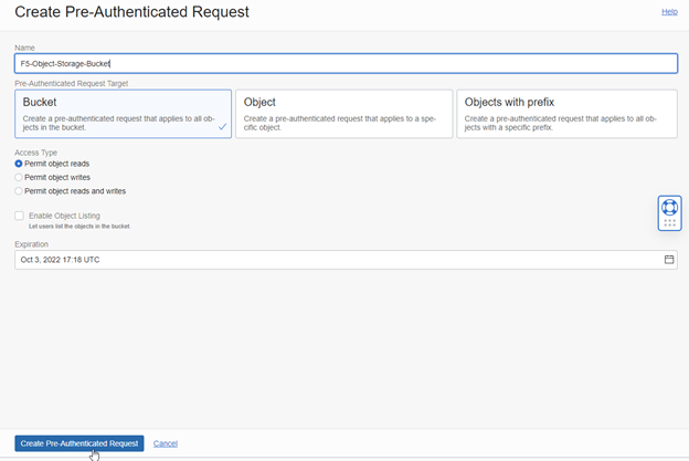
- Enter a Name for the Pre-Authenticated Request, set an expiration time, and leave all other settings at default click Create Pre-Authenticated Request as shown below. You can create a Pre-Authentication request for all objects in the bucket at a bucket level or can create one on the exact object when that is uploaded. In this, we have shown the Pre-Authenticated Request at the bucket level.
5. Copy the Pre-Authenticated Request URL. This may be needed when creating a custom image if you create the custom image using the URL. You will not need this if you select the object directly from the bucket.
6. Click on the Storage Bucket you just created in step 2 and on the left side menu click Objects. From there click Upload to upload the .qcow2 file we downloaded and unzipped earlier.
Create a Custom Image for F5 BIG-IP VE
Now we will need to create a custom image that will be used as the source for the BIG-IP VE instances.
- Under the Compute section, click Custom Images and then on Import Image.
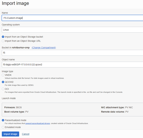
- Give the image a Name, select OS as Linux, select the bucket and object name, select QCOW2 as the Image Type, select Paravirtualized Mode if not already selected, and then click Import Image. Leave other settings at default.
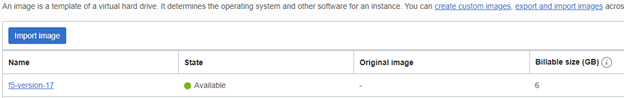
3. The process will take a few minutes to import. Once done you should see the state as Available and the size in GB as shown below.
Deploy a BIG-IP VE Instance
The next step is to deploy the BIG-IP VE instance from the custom image that was previously created. The instance will be referred to as F5-Primary. In our future post when we create a HA cluster, we will name the standby VE as F5-Secondary.
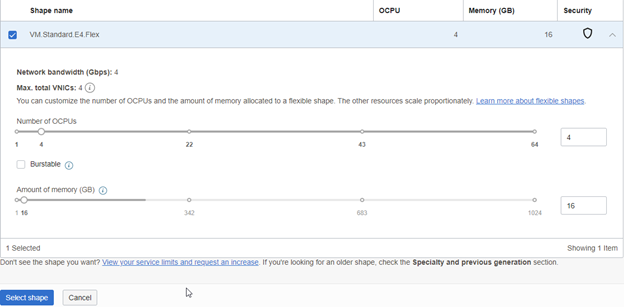
When you deploy the instance, you get to choose what image and shape you want to choose. The image in our case will be the custom image that we created earlier, and the shape will depend on how much horsepower is needed. For example, if you are deploying an instance with 2 OCPUs then you will get 2 VNICs only. So, to satisfy the requirements that we have for our setup, we will need 4 VNICs for the 4 subnets and hence we will need to select at least 4 OCPUs for our instance. The amount of Memory can be chosen based on the requirement. However, for these many CPUs in our case, a memory of at least 8GB will be required for us to run a LTM module. The amount of memory provisioned will depend on how many F5 modules like LTM, DNS, ASM, etc. will be deployed.
Also, note that the shape of an instance can be changed anytime in case you think the instance is over-provisioned or under-provisioned. The instance will however have to be rebooted for the new shape to take effect.
Here are the detailed steps:
- Click Instances under the compute section and then click Create Instance to start creating our VE instance.
- Provide a name for the instance i.e F5-Primary in our case, Choose the Availability Domain if that needs to be changed from the default.
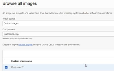
- Next, click Change Image and change the image source to a custom image and select the VE image that we created. Click Select Image.
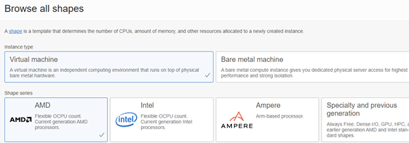
4. Click on Change Shape to adjust the CPU, Memory, Shape series and Instance type as shown below. Once all the parameters are selected click Select shape.
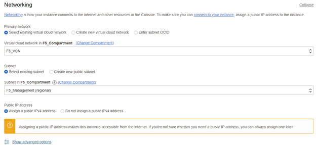
5. In the Networking section of the instance, select the appropriate VCN, Subnet and assign a Public IP address to the management interface.
6. Add any ssh keys for this instance either by generating a new pair or reusing a pair you already have. Leaving the rest of the options to the default settings click Create to create the instance.
7. Once the instance is ready it will appear in the list of Instances as Running as depicted below.
![]()
Create Additional VNICs
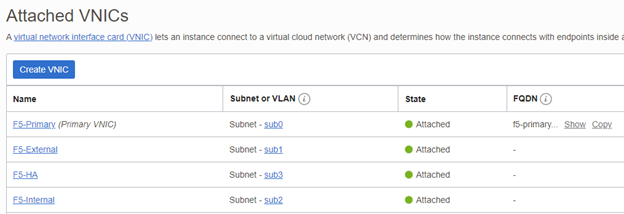
When the instance was created, a primary VNIC was automatically created. That VNIC is for management traffic as can be seen from the Networking section of the instance.
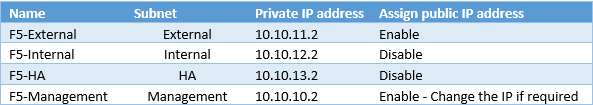
We will need to create 3 additional VNICs for the External, Internal and HA_sync subnets.
Click on the instance that was just created F5-Primary. On the left menu click Attached VNICs and create 3 additional VNICs as below. Each VNIC will be given an IP address based on our topology.
You must reboot the BIG-IP VE to recognize the additional VNICs. Click on the instance and then click reboot. Once the instance is back up ensure that you are able to reach the management IP address via the public IP address and can see the login prompt.
Once the instance is successfully deployed and the management IP is reachable over the Internet the next steps would be to configure the BIG-IP VE and then test. The steps for configuration will be covered in Part 3 of this series.
Conclusion
In this post, we successfully downloaded a BIG-IP VE image from the F5 downloads website, unzipped it and uploaded it to the Storage bucket and from there created a custom image. We then used the custom image created to deploy an instance of the BIG-IP VE based on the topology diagram reference. Choosing the right shape for the instance is a key aspect in this step. The shape will depend on how many OCPU’s, memory and VNICs are required to run the required F5 Modules. The more modules are run the higher the processing power of the instance is required.
We will cover the configuration of the BIG-IP VE instance in Part 3 of this series.