Introduction
In this this blog we are going to review some options to utilize FastConnect or IPSec Virtual Private Network (VPN) connectivity in two different Oracle Cloud Infrastructure (OCI) regions in a redundant manner.
In May of 2021 we announced new functionality available in our Dynamic Routing Gateway (DRG). One of the new supported features in that announcement was the ability for customers to access networks in one region through a FastConnect or VPN connection in a different region. This blog will dive into a few scenarios and options for customers to take advantage of this new feature. The example scenarios discussed below will use FastConnect as the connectivity method, but the same principles apply whether the connectivity is FastConnect or VPN.
For more information on the new DRG features, see the additional links section below.
Before we dive in to the scenarios, let’s briefly review some of the relevant DRG components that we’ll be covering.
DRG Attachment
The DRG is a virtual router that you attach various network resources to. You can attach Virtual Cloud Networks (VCN), Remote Peering Connections (RPC), Site-to-Site VPN IPSec Tunnels, or FastConnect Virtual Circuits (VC). To compare the DRG to a traditional physical router, I like to think of DRG attachments as the virtual equivalent to making physical connections on a traditional router. Attaching a VCN to your DRG would be similar to connecting your downstream LAN switch by plugging in your Local Area Network (LAN) cable to the physical router. Attaching the RPC or FastConnect would be similar to connecting your Wide Area Network (WAN) circuit by plugging in your WAN cable to the physical router.
DRG Route Tables
Each DRG attachment must have a DRG route table associated to that attachment and a single DRG route table can be shared between multiple attachments. When you create a new DRG the system will create two autogenerated route tables and apply them to your configuration for you. One autogenerated route table for RPC, VC, and IPSec attachments and another autogenerated route table for VCN attachments. These route tables will work as-is for most customer scenarios, however you can create your own DRG route tables and apply them to your specific attachments instead. We will have to create new DRG route tables in all of our scenarios below as the autogenerated ones will not accomplish the intended results.
Going back to our comparison of the DRG to a traditional physical router, there are some differences here with regards to these DRG route tables. A traditional physical router typically only has one single route table for the entire router and this route table will route packets in from one interface out to another interface based on the next hop in the route table. The DRG is a bit different in that there is a route table for each attachment, although multiple attachments can use the same route table. When a packet enters a DRG through an attachment, that attachment’s DRG route table and route rules are used to determine that packet’s next hop. It is in this way that we can use different route tables to help us manipulate and control the routing in the steps below.
DRG Route Distributions
A DRG route distribution is a list of declarative statements that contain a match criteria and an associated action. DRG route distributions are the mechanisms used to control what routes are imported to or exported from a DRG route table. DRG route tables contain both static and dynamic routes. Static routes are inserted into the DRG route table using the API and you can add them via the OCI console, while dynamic routes are imported from attachments and inserted into the DRG route table using an import route distribution. Export route distributions are used to control which routes are exported from a DRG route table to another attachment’s DRG route table, but as of the date of this blog post the use of non-default export route distributions is not supported. The default export route distribution for every DRG route table is to allow all routes to be exported. Therefore, in order to control the routing we must use import route distributions to accept or reject routes coming in to a DRG route table.
Using our same comparison of the DRG to a traditional physical router, think of DRG route distributions as being similar to route maps or policy statements that are used to control what routes are advertised (export route distribution) or received (import route distribution) in a traditional router.
For more information on the DRG and its components, see the additional links section below.
Basic Active/Passive
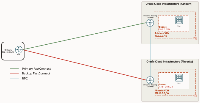
In this scenario, we have a single on premise location that will have a FastConnect to one region (Ashburn) and a 2nd FastConnect to another region (Phoenix). The redundancy design for this scenario is active/passive, meaning we want all traffic regardless of destination to go via the primary FastConnect (Ashburn) and the backup FastConnect (Phoenix) will only pass traffic if the primary FastConnect is down.
As mentioned in the Introduction section above, the autogenerated route tables and import route distributions for the Virtual Circuit, RPC, and IPSec attachments will not allow this active/passive behavior so we must create new ones. To make it simple and consistent, we will create 3 new route tables with 3 new import route distributions associated, one for VCN attachment, one for Virtual Circuit attachment and one for RPC attachment. These need to be created in each region and associated to the attachments in the region’s DRG.
| Attachment | DRG Route Table | Import Route Distribution |
|---|---|---|
| VCN Attachment | VCN RT | VCN IRD |
| Virtual Circuit Attachment | VC RT | VC IRD |
| RPC Attachment | RPC RT | RPC IRD |
The tables below show the route distribution statements that are needed in each of the 3 import route distributions. Basically, each import route distribution needs to have statements allowing the importing of routes from the other two attachments. Below we are using the match type Attachment Type, as an alternative you could select the match type as Attachment and select the specific attachment you want the routes imported from.
VCN IRD
| Priority | Match Type | Match Criteria |
|---|---|---|
| 1 | Attachment Type | Virtual Circuit |
| 2 | Attachment Type | Remote Peering Connection |
VC IRD
| Priority | Match Type | Match Criteria |
|---|---|---|
| 1 | Attachment Type | Virtual Cloud Network |
| 2 | Attachment Type | Remote Peering Connection |
RPC IRD
| Priority | Match Type | Match Criteria |
|---|---|---|
| 1 | Attachment Type | Virtual Circuit |
| 2 | Attachment Type | Virtual Cloud Network |
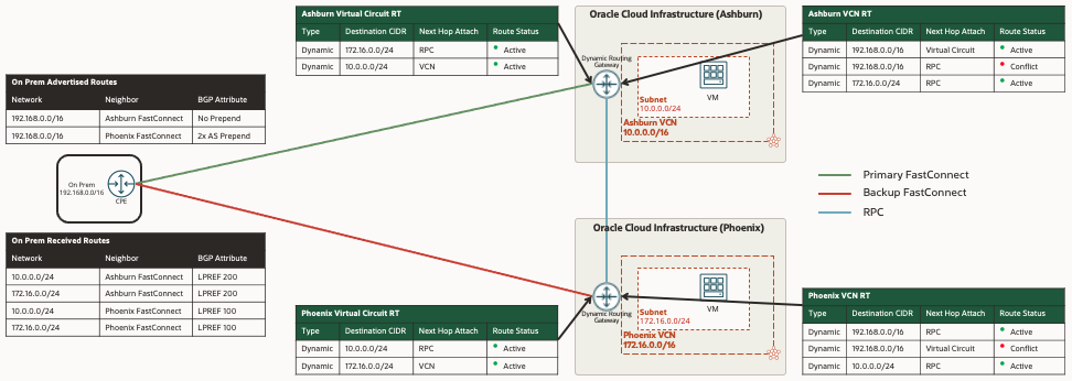
The above changes are needed on the OCI side, however we must also make changes on the on premise CPE using BGP attributes in order to make the Ashburn FastConnect the primary path and the Phoenix FastConnect the backup path. Oracle’s best practice recommendation is to use the BGP attributes Local Preference and AS Path to manipulate the routing in each direction. See the additional links section below for more information on Oracle’s Connectivity Redundancy Guide using BGP.
The black tables in the diagram below illustrate how we will accomplish this with BGP, and the green tables below are what the relevant OCI DRG route tables will look like to accomplish the active/passive. When both FastConnects are operational, all traffic in either direction or destinations will traverse the primary Ashburn FastConnect. If the primary Ashburn FastConnect were to go down, all traffic in either direction or destination will traverse the backup Phoenix FastConnect.
Active/Active – CPE Controls Routing via BGP Attributes
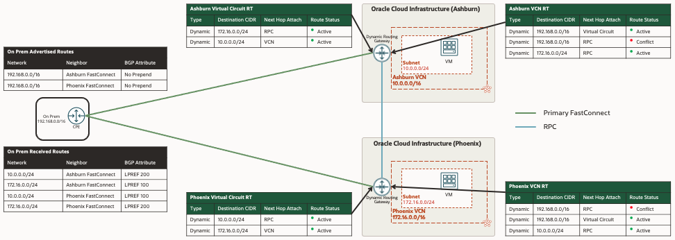
For this second scenario, we will build upon the active/passive scenario above, no changes will be required on the OCI side but we will change the BGP attributes being modified in the on premise CPE so that the two FastConnects are used in an active/active manor. The Ashburn FastConnect will be the primary symmetric path for all traffic from on premise destined for Ashburn and the Phoenix FastConnect will be the primary symmetric path for all traffic from on premise destined for Phoenix. Both FastConnects will be the backup path for each other.
Notice the difference with the BGP attributes being modified in the on premise CPE in the black tables compared to the Active/Passive scenario above in order to accomplish the Active/Active.
Active/Active – OCI Controls Routing via Summary Routes
Oracle’s recommendation for Active/Active is to control the routing using the on premise CPE with BGP attributes in the scenario above. I recently ran into a situation with a customer where the on premise CPE was not a router that the customer had direct control over and was limited to what BGP attributes it could support. They requested options for them to control the routing from the OCI side. At the time of this blog being written, Oracle does not support changing any of the BGP attributes such as Local Preference or AS Path on the OCI side. However we were able to accomplish this for them in a different way, leveraging the longest prefix match rule and using summary routes. The longest prefix match rule refers to a router’s decision making process of what route to use in its routing table when making a forwarding decision. The router will choose the route that is more specific – the one with the longest subnet mask. If you are not familiar with the longest prefix match, see the additional links section for more information.
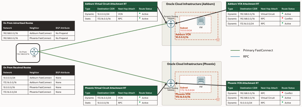
NOTE: By default, the DRG will advertise the specific VCN subnets over FastConnect or VPN and will not advertise the entire VCN CIDR. In order for this scenario to work, the VCN subnets must be smaller networks than the entire VCN CIDR. In our example, the VCN in Ashburn is 10.0.0.0/16 and the single subnet we have is smaller 10.0.0.0/24. If the VCN CIDR were to be 10.0.0.0/24 with a single subnet the same size 10.0.0.0/24 this scenario will not work.
In order to accomplish this, we have to make a couple changes to the DRG route tables and import route distributions we created in the active/passive scenario above. Below you will notice the new import route distributions for this scenario, the difference being that the VC IRD only has 1 statement importing routes from the VCN only. When we do this, the DRG will stop importing the VCN subnets it’s learning from the other region via the RPC. This is important because we do not want the DRG to advertise the specific /24 VCN route for the other region, only the specific /24 for it’s own VCN subnet.
VCN IRD
| Priority | Match Type | Match Criteria |
|---|---|---|
| 1 | Attachment Type | Virtual Circuit |
| 2 | Attachment Type | Remote Peering Connection |
VC IRD
| Priority | Match Type | Match Criteria |
|---|---|---|
| 1 | Attachment Type | Virtual Cloud Network |
RPC IRD
| Priority | Match Type | Match Criteria |
|---|---|---|
| 1 | Attachment Type | Virtual Circuit |
| 2 | Attachment Type | Virtual Cloud Network |
The other change we need to make is to add a static summary route in the VC RT in each region, pointing the VCN CIDR for the other region to the RPC. This summary route will be advertised over the FastConnect and will serve as the backup route and because of the longest prefix match rule, the CPE will not route traffic via this route unless the more specific /24 route is no longer there.
Ashburn VC RT Static Summary Route
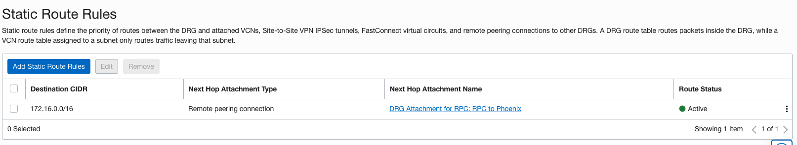
Phoenix VC RT Static Summary Route

Additional Links
OCI Connectivity Redundancy Guide