Prerequisites:
OCI Network Firewall – Concepts and Deployment
OCI Network Firewall – NAT Gateway use case
In this new blog post we will analyze one of the most used scenario, the Hub and Spoke topology with the OCI Network Firewall inspecting the North-South and East-West (inter and intra VCN) traffic.
The networking topology for the Hub and Spoke scenario is listed below:
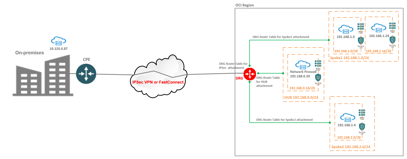
We have four cases that we will analyze from the configuration, traffic path and logs perspective:
Case 1
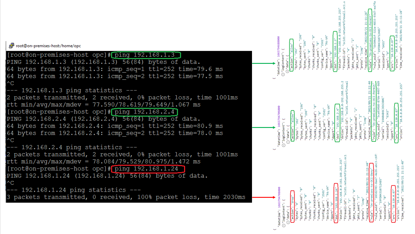
The traffic from On-premises VM at 10.120.0.87 to OCI VMs at 192.168.1.3 and 192.168.2.4 to be allowed and blocked to 192.168.1.24. All the traffic will pass through the OCI NFW at 192.168.0.20 for security enforcement. All the Security Lists at any subnet level are wide opened.
In this example, the connectivity between the OCI and On-premises is performed by using BGP over IPSec tunnels. The FastConnect can be used in the same fashion.
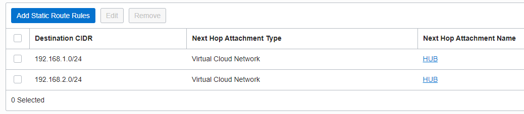
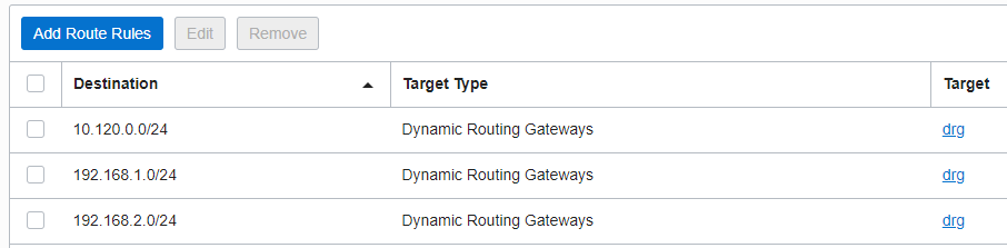
Once the traffic is received by the DRG from On-premises, it will use the DRG RT for the IPSec attachment to perform the routing of the packet. All the traffic from On-premises to any OCI VM needs to be analyzed by the NFW, the below entries are necessary for the packet to be sent to the HUB VCN where the NFW is located:
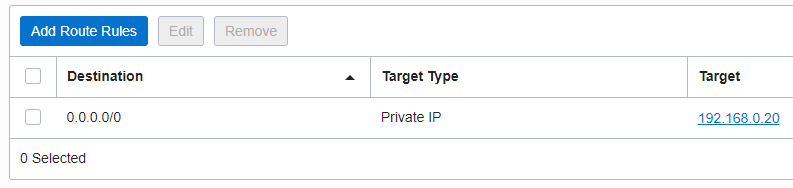
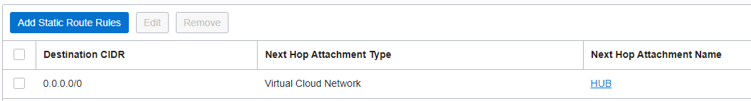
The VCN RT used by the DRG to direct the On-premises to OCI traffic has the following route entry:
Once the traffic reaches the NFW we will need the proper configuration to accomplish the scope defined above.
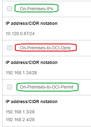
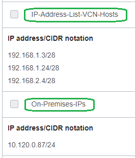
The NFW IP Address Lists matching the On-premises IP address and the OCI VMs IP addresses:
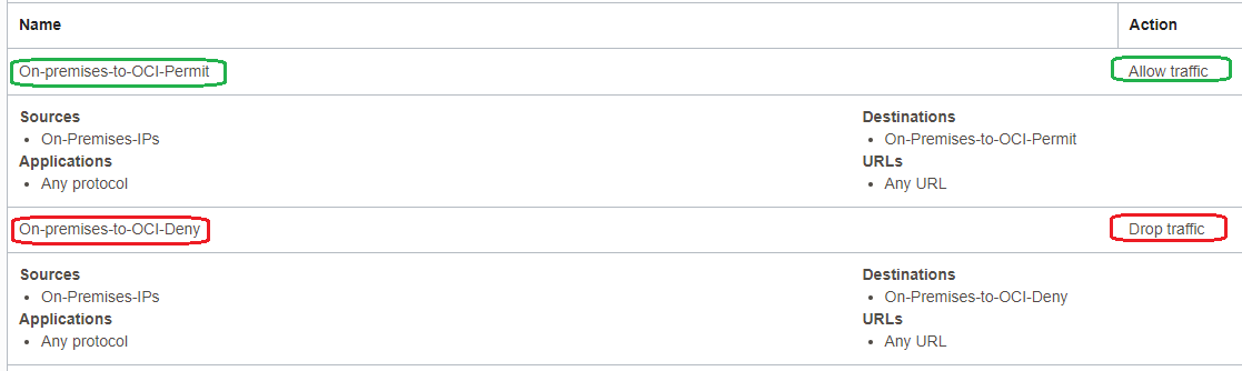
The NFW Security Rules:
After the traffic is inspected by the NFW and based on the action performed, the traffic needs to be forwarded to the destination (if the action was to allow it). The subnet RT of the NFW contains the following entries:
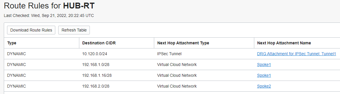
Once the analyzed traffic reaches the DRG, it will use the RT associated with the HUB VCN attachment for forwarding to the destination. The RT associated with the HUB VCN attachment contains the following entries dynamically learned:
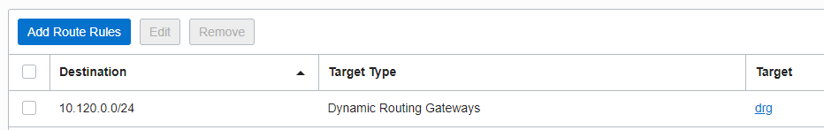
The route tables for all the subnets listed in the networking diagram contains the following route entry for sending the response traffic back to On-premises via the DRG:
Both the Spokes DRG RTs for VCN attachments contains the following route entry for the response traffic to be sent to the HUB VCN where the NFW is configured:
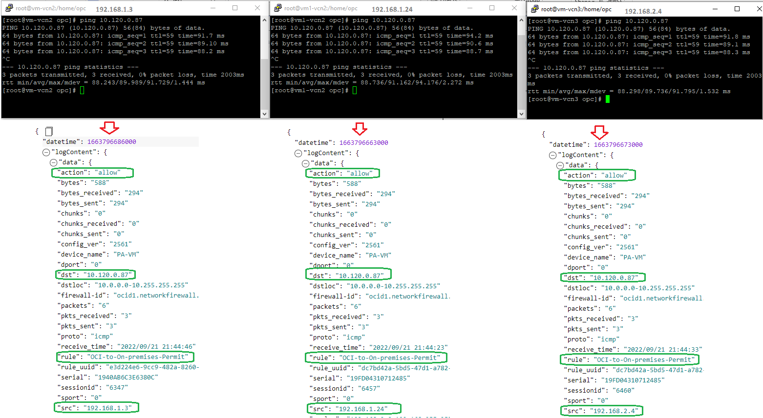
Now, we have all the routing and NFW configuration to accomplish the Case 1. To prove that all is working as expected let’s start the traffic from On-premises to the OCI and analyze the NFW logs.
Case 2
The traffic originated from any Spoke to On-premises must be allowed by the NFW.
From the routing configuration to accomplish this case nothing is needed. We only need to perform the NFW configuration.
The NFW IP Address Lists:
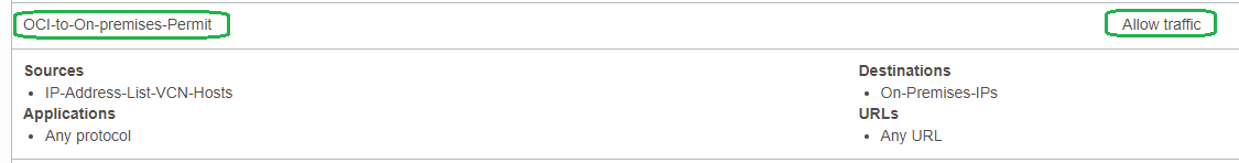
The NFW IP Security Rules:
Now, let’s test the traffic the VCN VMs to the On-premise host and analyze the logs:
The NFW configuration applied accomplished the Case 2 requirement.
Case 3
All the traffic between Spoke1 and Spoke2 needs to be allowed and analyzed by the NFW.
The individual subnets from Spoke1 needs to contain a new route entry in the associated RTs:

The subnet from Spoke2 needs to contain two new route entries in the associated RT:

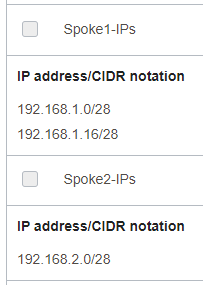
The NFW IP Address Lists:
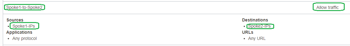
The NFW IP Security Rules:
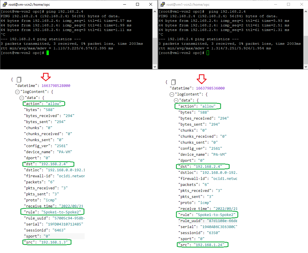
It is the time to test the traffic between Spoke1 and Spoke2 and make sure the traffic is analyzed by the NFW:
Case 4
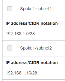
The traffic between 192.168.1.0/28 subnet and 192.168.1.16/28 subnet from Spoke1 VCN needs to be analyzed and allowed by the NFW.
To accomplish the scope, we need to add a route entry in each subnet RT as following.
On the 192.168.1.0/28 subnet RT:

On the 192.168.1.16/28 subnet RT:
![]()
The NFW IP Address Lists:
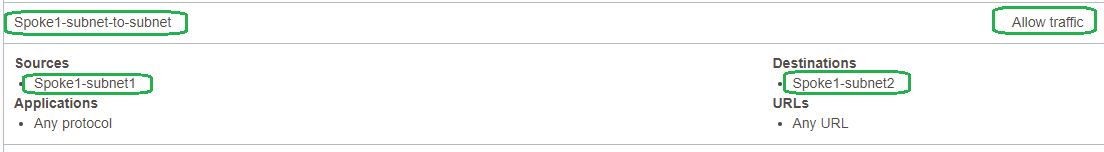
The NFW IP Security Rules:
Let’s send some traffic:
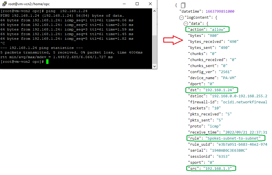
As we expected, the configuration applied is directing the traffic between Spoke1 subnets through the NFW.