Prerequisites:
OCI Network Firewall – Concepts and Deployment
We will continue the blog series dedicated to the OCI Network Firewall and we will analyze a brand new use case. The new use case includes the NAT Gateway in the picture and allowed/denied traffic from the VCN VMs to an Internet Web Server based on source/destination IP addresses and NFW URL filtering.
The networking topology used is listed below:
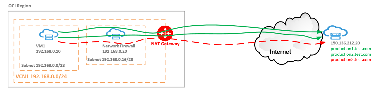
The VM at 192.168.0.10 will initiate TCP connections on port 443 to an Internet Web Server located at 150.136.212.20. The Web Server is hosting three production sites. VM1 is allowed to connect to production1 and production2 but not to production3. Any connection attempt to any of the sites needs to be logged no matter if the connections is allowed or not.
The first point we need to discuss is the routing inside the VCN to permit the traffic to flow in the proper order to accomplish the scope defined above:
VM1 -> NFW -> NAT Gateway -> Internet Web Server for the initiated traffic and Internet Web Server -> NAT Gateway -> NFW -> VM1 for the response traffic.
As we know from the preceding blog, the route table associated with the VM1 contains the following routing rule:
The rule will assure that all the traffic initiated by the VM1 will be sent to the NFW for inspection.
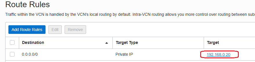
The route table associated with the NFW subnet (192.168.0.16/28) contains a route rule which sends all the traffic for the 150.136.212.20 destination to the NAT Gateway:
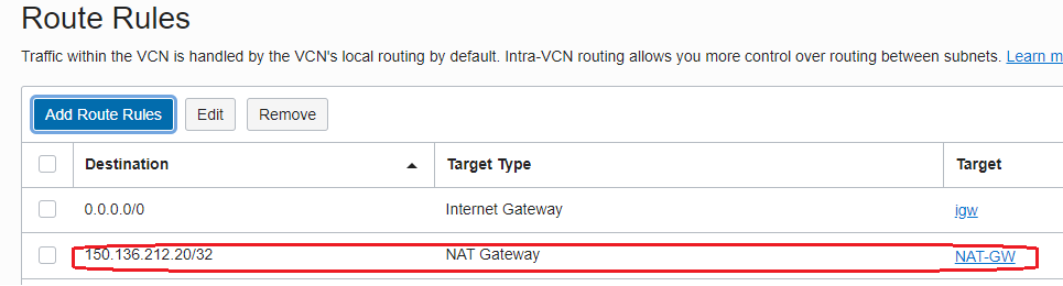
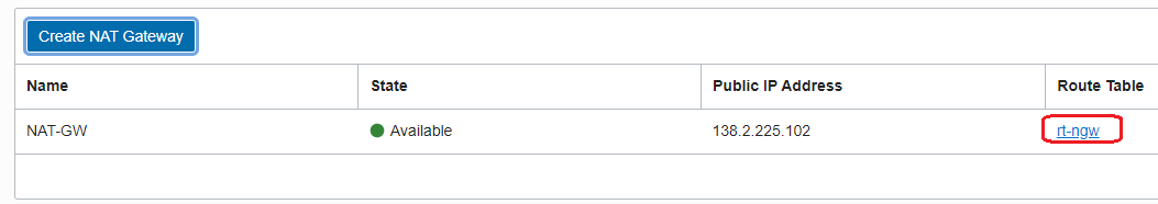
In order for the NAT Gateway to send the response traffic back to the NFW, we need to create a route table and attach the new route table to the NAT Gateway. In our previous blog we explored this function for the Internet Gateway, the same feature is also available for the NAT Gateway:
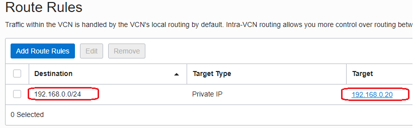
The route table attached to the NAT Gateway contains a route entry for the VM1 subnet through the private IP address of the NFW:
Now, as we correctly configured the routing, let’s proceed with the NFW policy that will accomplish the above scope:
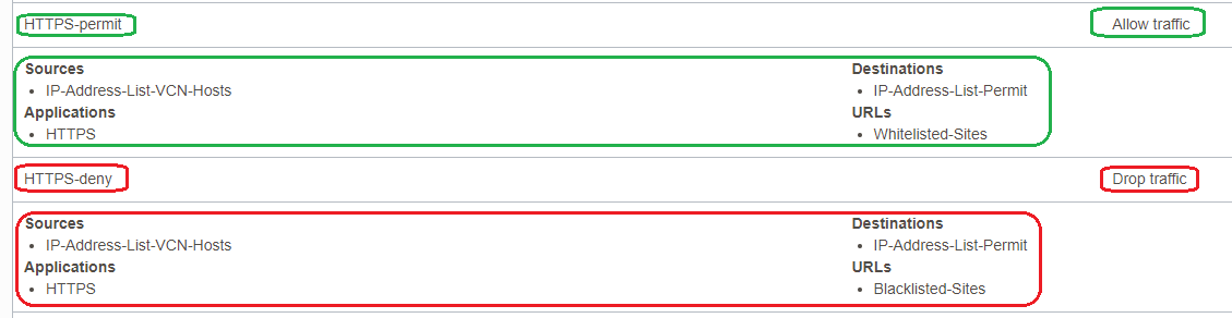
a) allow the traffic from 192.168.0.10 to 150.136.212.20 for production1.test.com and production2.test.com on TCP port 443 and log the traffic:
b) deny the traffic from 192.168.0.10 to 150.136.212.20 for production3.test.com on TCP port 443 and log the traffic;
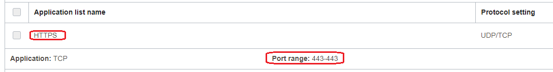
1. Define the Application:
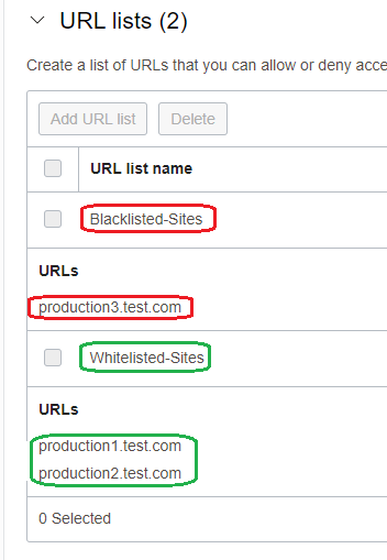
2. Define the URLs List:
3. Define the Security Rules:
Apply the policy to the NFW and wait for policy to be applied (roughly between 5-10 minutes).
It is the time to test our configuration and verify the NFW logs:
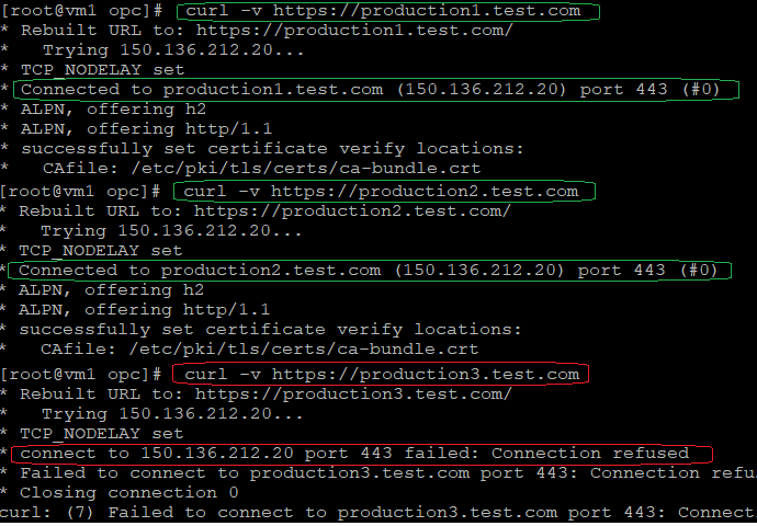
As we can see from the above curl commands, the connection is being established for production1 and 2 but not for production3.
Let’s verify our NFW logs for evidence:
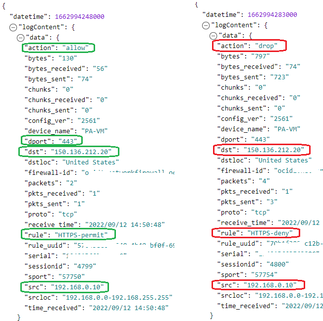
That is working as expected!