Dealing with multiple routing domains, especially when we need to create a cloud based networking architecture with firewalls is not something we encounter on a daily basis. Routing domains sounds more like on-premises traditional networking routing and security segregation which requires some more advanced routing and security functions and configuration to be in place. Few months ago I was pleased to handle a customer project where I was able to “migrate” the routing domain configuration from On-premises to OCI maintaining 90% of the On-premises capabilities. This type of request is challenging any cloud provider routing and security engines, however, OCI with its DRG routing capabilities and third party firewall marketplace vendor accomplished it successfully.
It is a very interesting use case, quite different from other networking requests to receive/analyze/action using an Inspection or Security VCN within OCI. We will discuss this advanced routing topic including the networking approach and design used, traffic testing and conclusions in a two part blogs. I decided to have two parts, since in the first one, we need to analyze and understand the customer request and approach and in the second one, we will deal with the traffic testing and conclusions.
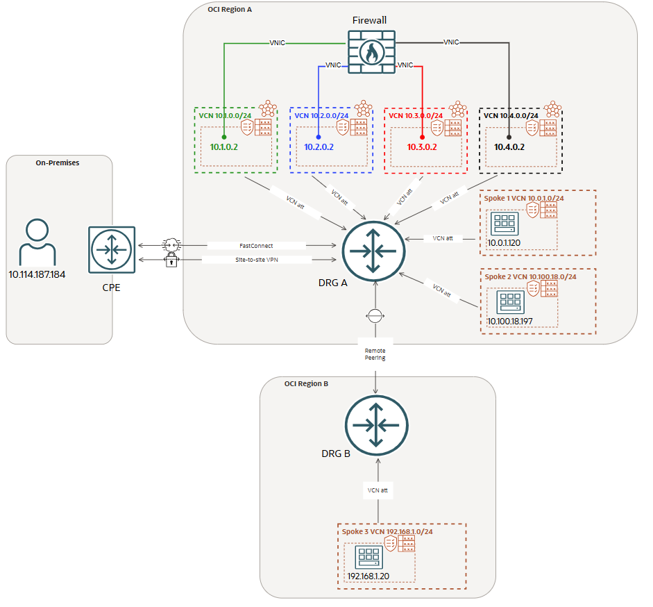
After we had the technical meetings to discuss the requirements, the following simplified networking diagram was proposed and validated. It does not contain all the services and configuration, what is contains is the core of the routing and security configuration that accomplish the customer use case. Let’s analyze it and understand the multiple routing domains posture.
The most important part is to understand what the routing domain concept means for our use case. We have defined above four entities: 1. On-premises; 2. RPC; 3. Spoke 1; 4. Spoke 2.
Let’s define the communication between any two entities above. e.g: On-premises to Spoke 1, On-premises to Spoke 2, On-premises to Spoke 3, Spoke 1 to Spoke 2, Spoke 1 to On-premises and so on. Ok, fair enough, what is so special with the communication between the above entities? That’s a good question. For having a simplified diagram still maintaining the core of the solution, we have one firewall with four VNICs. Each VNIC will be used for a specific direction of the traffic.
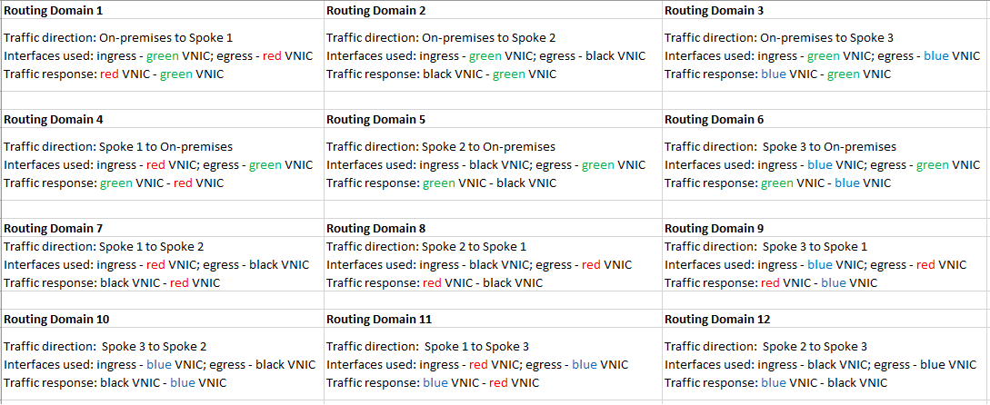
The traffic direction (using only specific VNICs) together with the communication between entities explained above will define a routing domain.
As we may notice, the four firewall VNICs are configured in different VCNs (green, blue, red, black) attached to the DRG. Each VNIC is associated with an ingress traffic flow and a given interface must not be used for egressing the traffic if previously was used for ingress.
For our current networking topology, the communication requested will create the following routing domains (traffic direction together with the interfaces used):
Defining the routing domains as above will match the security and routing configuration from On-premises routers and firewalls. Each and every firewall interface will migrate the On-premises configuration and the logs will be extracted in a very granular way.
As we can observe, in the above table, each routing domain is using one firewall interface for ingress and one interface for egress. This will also increase the overall throughput, another benefit using this approach.
Dealing with a complex routing scenario we need to use the most of the advanced DRG routing functions. In the following section we will highlight the configuration we need on the DRG to perform the above routing posture. The step-by-step DRG routing configuration will be presented in the next part of the blog, now we only need to have an overview of the routing functions we will use.
The connection to On-premises can use the FastConnect or IPSec VPNs. The DRG attachment for FastConnect or IPSec VPN will use its own DRG attachment route table. This route table will not have the Route Distribution Import attached since all the traffic that needs to flow from On-premises to Spoke 1/2/3 must use the green interface as ingress interface. We will direct this traffic to the VCN where the green interface is configured by using the DRG green VCN route table with the next-hop of 10.1.0.2 (transit routing).
Spoke 1 and Spoke 2 attached to the DRG will have their own DRG VCN attachment route table and we can just configure a default route with the next-hop attachment configured in the following way:
Spoke 1 – default route with next-hop attachment the red VCN
– direct this traffic to the VCN where the red interface is configured by using the DRG red VCN route table with the next-hop of 10.3.0.2 (transit routing)
Spoke 2 – default route with next-hop attachment the black VCN
– direct this traffic to the VCN where the black interface is configured by using the DRG black VCN route table with the next-hop of 10.4.0.2 (transit routing)
The traffic from Spoke 3 to any destination in the networking diagram will use the RPC together with the blue VCN for transit routing and the blue interface as ingress interface used for traffic inspection. The DRG RPC attachment route table will contain a route to 10.0.0.0/8 with the next-hop attachment the blue VCN. We will direct this traffic to the VCN where the blue interface is configured by using the DRG blue VCN route table with the next-hop of 10.2.0.2 (transit routing).
What about the green, blue, red and black VCNs where our Firewall interfaces used ingress/egress and traffic inspection points are configured. These VCNs will be attached to the DRG and given the fact that when egressing the traffic each VCN attachment route table needs to have knowledge for all the destinations, it is just fine to use the same VCN attachment route table where the Route Distribution Import associated will import Spoke 1, Spoke 2, RPC and FastConnect or IPSec VPN.
We still need to discuss about the routing inside our Firewall appliance. We know that specific destinations needs to be reachable over a specific interface, so, another point that needs our attention is the routing configuration in the Firewall appliance. The needed configuration is the following:
– On-premises will be reachable over the green interface
– Spoke 1 will be reachable over the red interface
– Spoke 2 will be reachable over the black interface
– Spoke 3 will be reachable over the blue interface
In the next part of the blog we will go through the configuration and traffic testing to prove that everything is working as expected.
Do you think that the above request can be accomplished with just one VCN containing all the Firewall interfaces? Just let me know your opinion.