Introduction
I recently worked with a customer that was replacing an existing FastConnect with a new one and their request was to migrate to the new FastConnect in an outage window, test the connection, and if the tests were successful they would run it in production for a few days before disconnecting the old FastConnect. If a problem happened during those few days, they wanted the ability to fallback to the old FastConnect very quickly and easily. Before the release of the expanded Dynamic Routing Gateway (DRG), the only way to accomplish this would be to manipulate and control the routing from the Customer Premises Equipment (CPE) end of the FastConnect Border Gateway Protocol (BGP) session. The CPE end of the BGP session for this customer was their managed network service provider which the customer did not directly have access to the BGP configuration. For them to manipulate and control the routing from that BGP peer, it would require them to open a ticket with the managed network service provider in advance and their concern was if there was an issue on the new FastConnect after cutover, their fallback to the old FastConnect may be delayed. The ask to me was whether they can control this cutover and fallback themselves on the OCI side and not require any involvement from the service provider.
This in fact can be done with the expanded DRG and in this blog post we are going to discuss the concepts and steps necessary to accomplish this. The steps outlined below will focus specifically on an example using IPSec Virtual Private Network (VPN)for both the existing and the new connection, but the steps can be applied to either IPSec VPN or FastConnect.
Before we dive in to the example, let’s briefly review some of the relevant DRG components that we’ll be covering.
DRG Attachment
The DRG is a virtual router that you attach various network resources to. You can attach Virtual Cloud Networks (VCN), Remote Peering Connections (RPC), Site-to-Site VPN IPsec Tunnels, or FastConnect Virtual Circuits (VC). To compare the DRG to a traditional physical router, I like to think of DRG attachments as the virtual equivalent to making physical connections on a traditional router. Attaching a VCN to your DRG would be similar to connecting your downstream LAN switch by plugging in your Local Area Network (LAN) cable to the physical router. Attaching the RPC or FastConnect would be similar to connecting your Wide Area Network (WAN) circuit by plugging in your WAN cable to the physical router.
DRG Route Tables
Each DRG attachment must have a DRG route table associated to that attachment and a single DRG route table can be shared between multiple attachments. When you create a new DRG the system will create two autogenerated route tables and apply them to your configuration for you. One autogenerated route table for RPC, VC, and IPSec attachments and another autogenerated route table for VCN attachments. These route tables will work as-is for most customer scenarios, however you can create your own DRG route tables and apply them to your specific attachments instead.
Going back to our comparison of the DRG to a traditional physical router, there are some differences here with regards to these DRG route tables. A traditional physical router typically only has one single route table for the entire router and this route table will route packets in from one interface out to another interface based on the next hop in the route table. The DRG is a bit different in that there is a route table for each attachment, although multiple attachments can use the same route table. When a packet enters a DRG through an attachment, that attachment’s DRG route table and route rules are used to determine that packet’s next hop. It is in this way that we can use different route tables to help us manipulate and control the routing in the steps below.
NOTE: A VCN attachment is the only attachment that has two route tables. The first is the DRG route table for the VCN attachment that behaves in the above fashion. As packets enter the DRG from the VCN attachment, the DRG route table for the VCN attachment is used to provide next hop details. The second is the VCN route table for the VCN attachment which is used for packets leaving the DRG through the VCN attachment. Applying a VCN route table is optional, and if not applied, a hidden implicit table always provides connectivity to all the subnets in the VCN. A VCN route table applied to the VCN attachment is required to enable transit routing.
DRG Route Distributions
A DRG route distribution is a list of declarative statements that contain a match criteria and an associated action. DRG route distributions are the mechanisms used to control what routes are imported to or exported from a DRG route table. DRG route tables contain both static and dynamic routes. Static routes are inserted into the DRG route table using the API and you can add them via the OCI console, while dynamic routes are imported from attachments and inserted into the DRG route table using an import route distribution. Export route distributions are used to control which routes are exported from a DRG route table to another attachment’s DRG route table, but as of the date of this blog post the use of non-default export route distributions is not supported. The default export route distribution for every DRG route table is to allow all routes to be exported. Therefore, in order to control the routing we must use import route distributions to accept or reject routes coming in to a DRG route table.
Using our same comparison of the DRG to a traditional physical router, think of DRG route distributions as being similar to route maps or policy statements that are used to control what routes are advertised (export route distribution) or received (import route distribution) in a traditional router.
See the below link for more detailed information on the DRG and it’s components:
https://docs.oracle.com/en-us/iaas/Content/Network/Tasks/managingDRGs.htm
Example Scenario
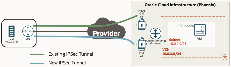
In our example we are going to use a simple scenario with a customer location that has two IPSec VPN tunnels going from on premise to the same OCI region and DRG. One tunnel is the existing IPSec tunnel that is carrying all of the production traffic, and the other tunnel is the new IPSec tunnel that we want to cut the traffic over to.
NOTE: Although this example uses an IPSec tunnel for both the existing and new connection, the same steps below can be followed whether the existing or new connection is an IPSec VPN or a FastConnect Virtual Circuit. The only difference is you would be applying your changes to a Virtual Circuit attachment instead of an IPSec attachment.
Prior To The Cutover
We will assume that prior to the cutover, the existing and new IPSec tunnels have already been provisioned and are up with BGP established. The below table outlines the DRG attachments, route tables, and import route distributions that are applied prior to the cutover.
| Attachment | DRG Route Table | Import Route Distribution |
|---|---|---|
| VCN Attachment | VCN RT | VCN IRD – Existing IPSec |
| IPSec Attachment for Existing Tunnel | Active IPSec RT | Active IPSec IRD |
| IPSec Attachment for New Tunnel | Inactive IPSec RT | <none> |
You will notice that each attachment has it’s own unique DRG route table and import route distribution and not using the autogenerated ones. This is required as we want to be very specific with what we want each of the attachments to import into their route table and advertise to any peers.
As with most routing scenarios, we need to look at both directions for routing. For traffic going from the VCN to on premise, before the cutover the “VCN RT” needs to see the route for the on premise subnet (10.0.0.0/28) over the existing IPSec tunnel and not over the new IPSec tunnel. For traffic going from on premise to the VCN, before the cutover the CPE needs to see the route for the VCN (10.0.2.0/28) over the existing IPSec tunnel and not over the new IPSec tunnel. After the cutover, we want to see the exact opposite where we see the routes in both directions over the new IPSec tunnel, but not over the existing IPSec tunnel.
Inbound Routes From On Premise to VCN
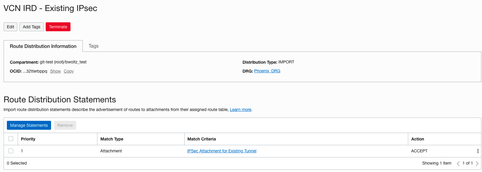
Remember that a packet entering a DRG through an attachment is routed using rules in the DRG route table associated to that attachment. Therefore the “VCN RT” associated with the VCN attachment should have the route for the on premise network 10.0.0.0/28 with the existing IPSec tunnel as the next hop. In the screenshot below you can see how we accomplish this. The “VCN IRD – Existing IPSec” import route distribution has a single statement that only allows routes from the existing IPSec tunnel to be imported. There is no statement in this import route distribution to accept any routes from the new IPSec tunnel so those will be rejected and not imported into the “VCN RT”.
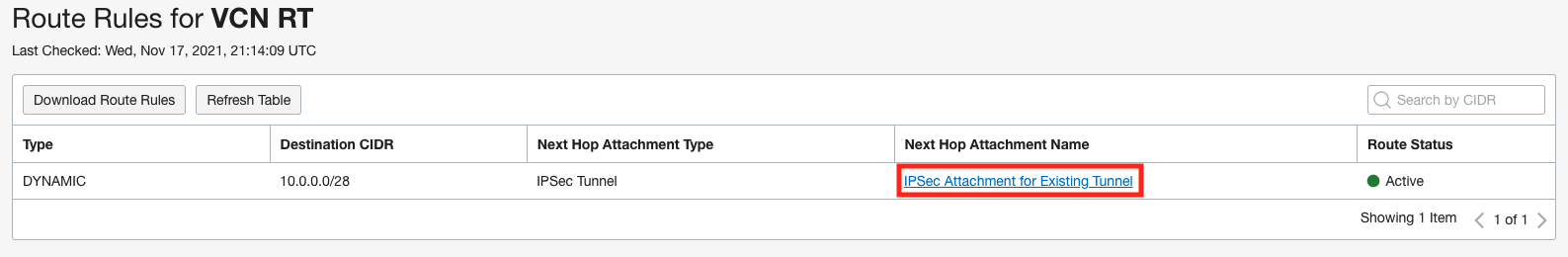
To verify this, we can view the route table for “VCN RT” by clicking on the route table and the “Get All Route Rules” at the top. Below is a view of the “VCN RT” and you can see the only route in there is from the existing IPSec tunnel.
Outbound Routes From VCN to On Premise
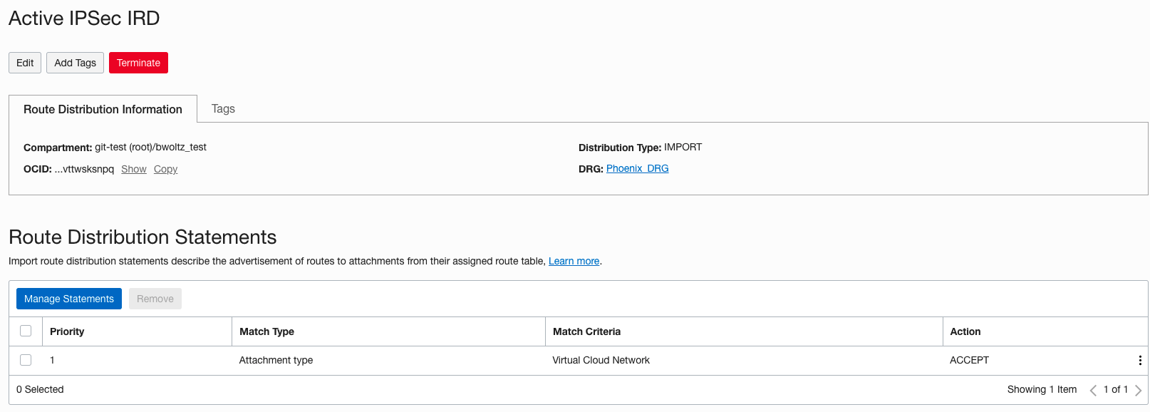
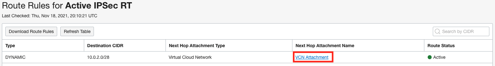
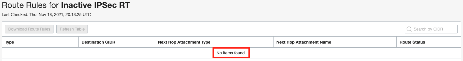
Remember that a packet entering a DRG through an attachment is routed using rules in the DRG route table associated to that attachment. Therefore the “Active IPSec RT” associated with the existing IPSec tunnel should have the route for the VCN 10.0.2.0/28 with the VCN as the next hop. In addition, the “Inactive IPSec RT” associated with the new IPSec tunnel should not have the route for the VCN. In the screenshots below you can see how we accomplish this. The “Active IPSec IRD” import route distribution has a single statement that only allows routes from the VCN to be imported and is associated with the “Active IPSec RT” route table. The “Inactive IPSec RT” route table is not associated to any import route distribution which means that no routes from any other attachments are imported.
To verify this, we can view the route tables for “Active IPSec RT” and “Inactive IPSec RT” by clicking on the route tables and the “Get All Route Rules” at the top. Below is a view of both route tables showing a route for the VCN on the Active IPSec RT and the Inactive IPSec RT is blank.
After The Cutover
From the previous section you can see how we used the DRG route tables and import route distributions to control the routing for both directions to use the existing IPSec tunnel for all traffic between the on premise location and the VCN prior to the cutover. Now we will outline the changes necessary to swing the traffic over to the new IPSec tunnel for both directions. The changes we will be making are also highlighted in the below table to easily compare with the pre cutover setup.
| Attachment | DRG Route Table | Import Route Distribution |
|---|---|---|
| VCN Attachment | VCN RT | VCN IRD – New IPSec |
| IPSec Attachment for Existing Tunnel | Inactive IPSec RT | <none> |
| IPSec Attachment for New Tunnel | Active IPSec RT | Active IPSec IRD |
Inbound Routes From On Premise to VCN
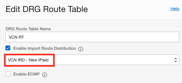
Remember that a packet entering a DRG through an attachment is routed using rules in the DRG route table associated to that attachment. Therefore the “VCN RT” associated with the VCN attachment should have the route for the on premise network 10.0.0.0/28 with the new IPSec tunnel as the next hop. We will accomplish this by creating a new import route distribution “VCN IRD – New IPsec” that has a single statement that only allows routes from the new IPSec tunnel to be imported and then applying that import route distribution to the “VCN RT”. To change the import route distribution associated to a route table, go into the route table and click the edit button and you will see the “Enable Import Route Distribution” drop down annotated in the below screenshot.
NOTE: An alternative way to accomplish this is to edit the existing import route distribution and remove the statement that accepts routes from the existing IPSec tunnel and add a new one that accepts routes from the new IPSec tunnel. Either way will work, the point is the route table associated with the VCN must accept the route for the on premise network over the IPSec tunnel that you want the traffic to use and you use the import route distribution to control this.
Outbound Routes From VCN to On Premise
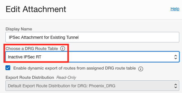
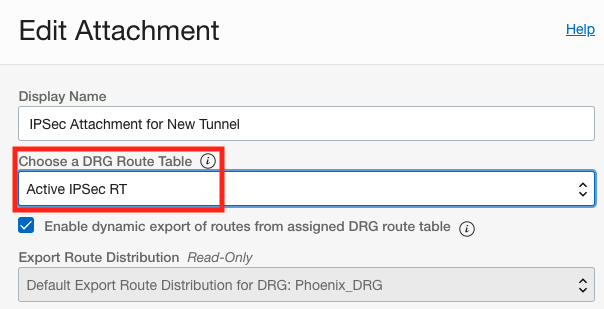
Remember that a packet entering a DRG through an attachment is routed using rules in the DRG route table associated to that attachment. Therefore the route table associated with the new IPSec tunnel should have the route for the VCN 10.0.2.0/28 with the VCN as the next hop. In addition, the route table associated with the existing IPSec tunnel should not have the route for the VCN. We will accomplish this by simply swapping the route tables that are associated with the two IPSec tunnels. The new IPSec tunnel will now have the “Active IPSec RT” associated it and the existing IPSec tunnel will now have the “Inactive IPSec RT” associated with it. To change the route table associated to the IPSec attachments, go to the IPSec attachment and click the edit button and you will see the “Choose a DRG Route Table” drop down annotated in the below screenshots.
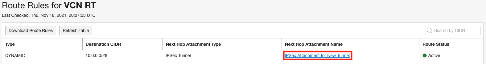
To verify the changes, we can go into each of the 3 route tables and click on the “Get All Route Rules” button to view the routing table. Below are the 3 routing tables showing the VCN route table has the route for the on premise network over the new IPSec tunnel, the new IPSec tunnel route table has the route for the VCN, and the existing IPSec tunnel route table is empty.
NOTE: An alternative way to accomplish this is to edit the existing route tables and disassociate the import route distribution on the existing IPSec tunnel route table and associate the “Active IPSec IRD” import route distribution on the new IPSec tunnel route table. Either way will work, the point is the route table associated with the IPSec tunnel that you want the traffic to use must accept the route for the VCN and the route table associated with the IPSec tunnel that you don’t want the traffic to use must reject the route for the VCN and you use the import route distribution to control this.
Fallback
Moving the traffic back to the existing IPsec tunnel is now very simple as we just need to reverse the changes and put the route tables and import route distributions back to the way they were prior to the cutover as outlined in the table below.
| Attachment | DRG Route Table | Import Route Distribution |
|---|---|---|
| VCN Attachment | VCN RT | VCN IRD – Existing IPSec |
| IPSec Attachment for Existing Tunnel | Active IPSec RT | Active IPSec IRD |
| IPSec Attachment for New Tunnel | Inactive IPSec RT | <none> |