It’s common for customers to leverage a third-party firewall in Oracle Cloud Infrastructure (OCI) to inspect North-South traffic (inbound and outbound) traffic. This is often implemented using a Hub-and-Spoke architecture.
We are assuming you have a basic understanding of networking, and you are familiar with OCI Networking (DRG, VCNs, subnets, security lists and routing).This guide focuses exclusively on traffic segregation. For demonstration, we use a single FortiGate instance. However, to achieve high availability, FortiGate instances can be deployed across availability or fault domains.
If high availability is a requirement, refer to this guide on setting up FortiGate in HA and then return here to continue.
You can also watch the video below for a complete walk-through of this process:
This article focuses on the below two use cases:
Usecase1: Inbound traffic inspection for accessing applications hosted in the Spoke1 VCN from the internet and on-premises.
Usecase2: Outbound traffic inspection for Spoke VMs to access the internet and on-premises.
- The following topology has been setup on the OCI:
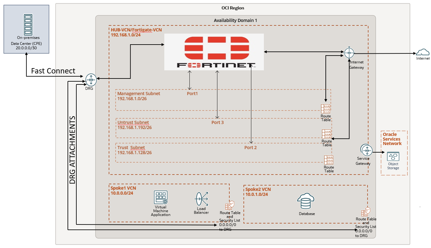
Hub VCN (192.168.1.0/24) contains a Fortinet FortiGate Firewall VM with three subnets—management, trust, and untrust.
- Management Subnet (192.168.1.0/26): Uses the primary interface (port 1) for user interface access.
- Trust Subnet (192.168.1.128/26): Uses the second interface (port 2) for internal traffic.
- Untrust Subnet (192.168.1.192/26): Uses the third interface (port 3) for external traffic.
The hub VCN includes the following communication gateways:
- Internet Gateway: Connects external web clients to the FortiGate firewall via the untrust subnet.
- Dynamic Routing Gateway (DRG): Links customer data centers router (20.0.0.0/30) over Fast Connect and enables VCN-to-VCN communication.
- Service Gateway: Connects the hub VCN to OCI Object Storage and other regional Oracle services.
We have two spoke VCN’s Spoke1 and Spoke2:
Spoke1 VCN (Web/App 10.0.0.0/24): Contains subnets for applications (NGNIX server used in this article to host webservices) and load balancers, connected to the hub VCN via DRG.
Spoke2 VCN (Database 10.0.1.0/24): Contains a database subnet, connected to the hub VCN via DRG.
2. Deploy FortiGate in HUB VCN using OCI marketplace . For this article I have used
Firmware: v7.6.0 build3401 (Feature)
Mode: NAT
You can also refer this link for deploying FortiGate in OCI.
How to deploy FortiGate in OCI.?
Setting up FortiGate.
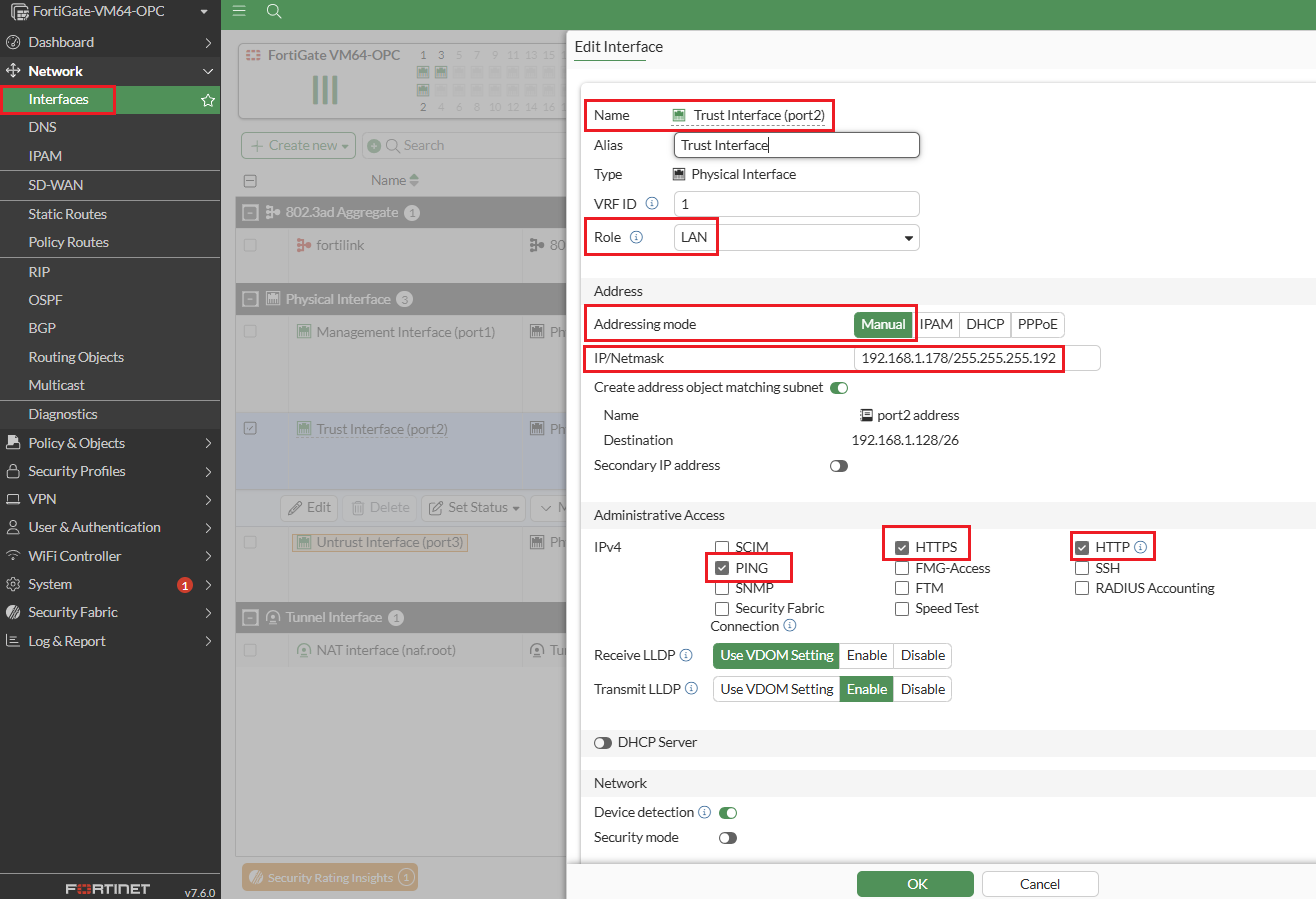
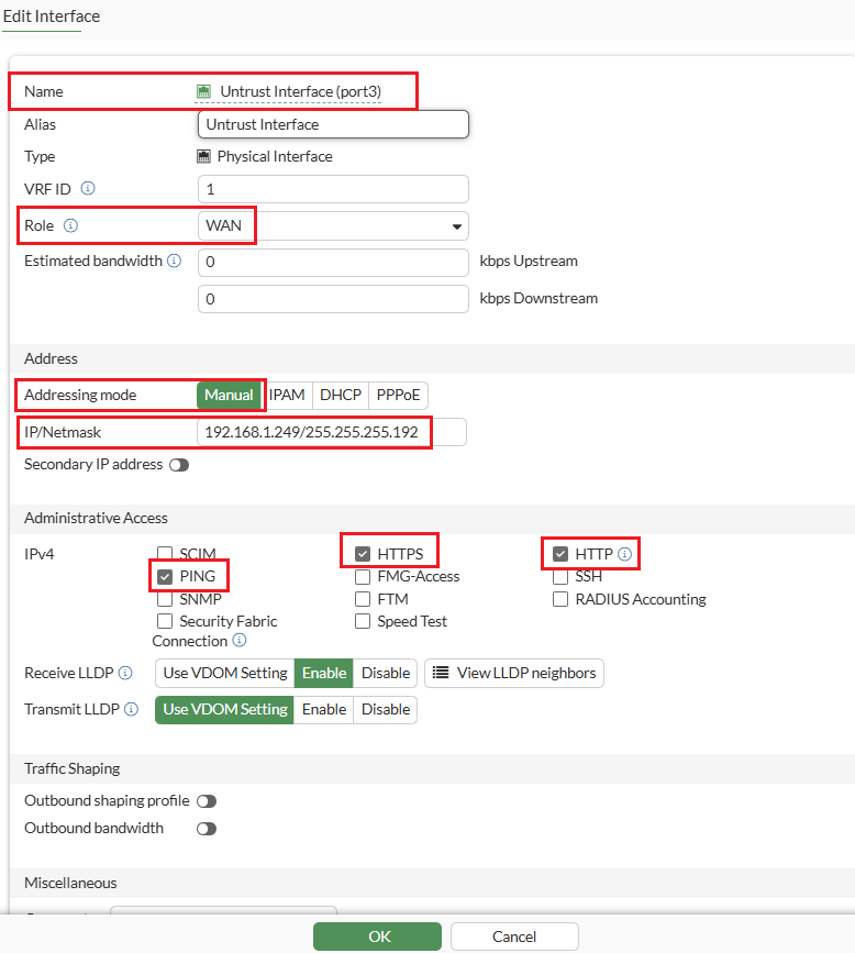
Step-1: Configure the interfaces by selecting “addressing mode” manual option. You can refer to the image for configuration details.
Trust-VNIC IP: 192.168.1.178
Default-GW IP: 192.168.1.1
Untrust-VNIC IP :192.168.1.249
Default-GW IP :192.168.1.193
Note1: The management interface is already configured with DHCP, so manual IP assignment is not needed.
Note2: Make sure to CHECK the box Skip Source/Destination Check for trust and untrust interfaces on OCI console.
Note3: By default, the MTU size of FortiGate interfaces is 1500.
Step 2: Now that we have the Firewall interfaces configured, we can setup the Hub and Spoke architecture on the OCI Console and use (Trust-VNIC IP: 192.168.1.178) as private IP for configuring Ingress routing for HUB VCN DRG attachment.
For more information on transit routing through private IP.
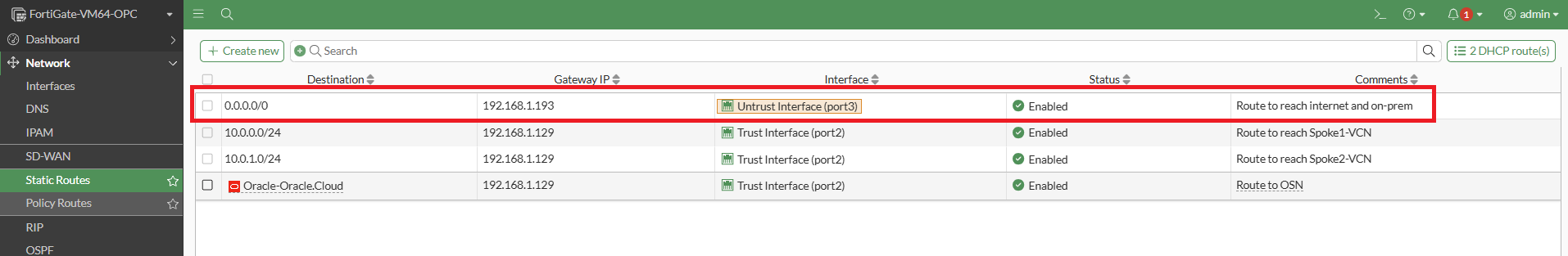
Step 3: Configure Static routing as shown in screenshot below. The purpose of each route is explained in the comments section. For the use cases discussed in this article, the static route highlighted in the red box will be utilized.
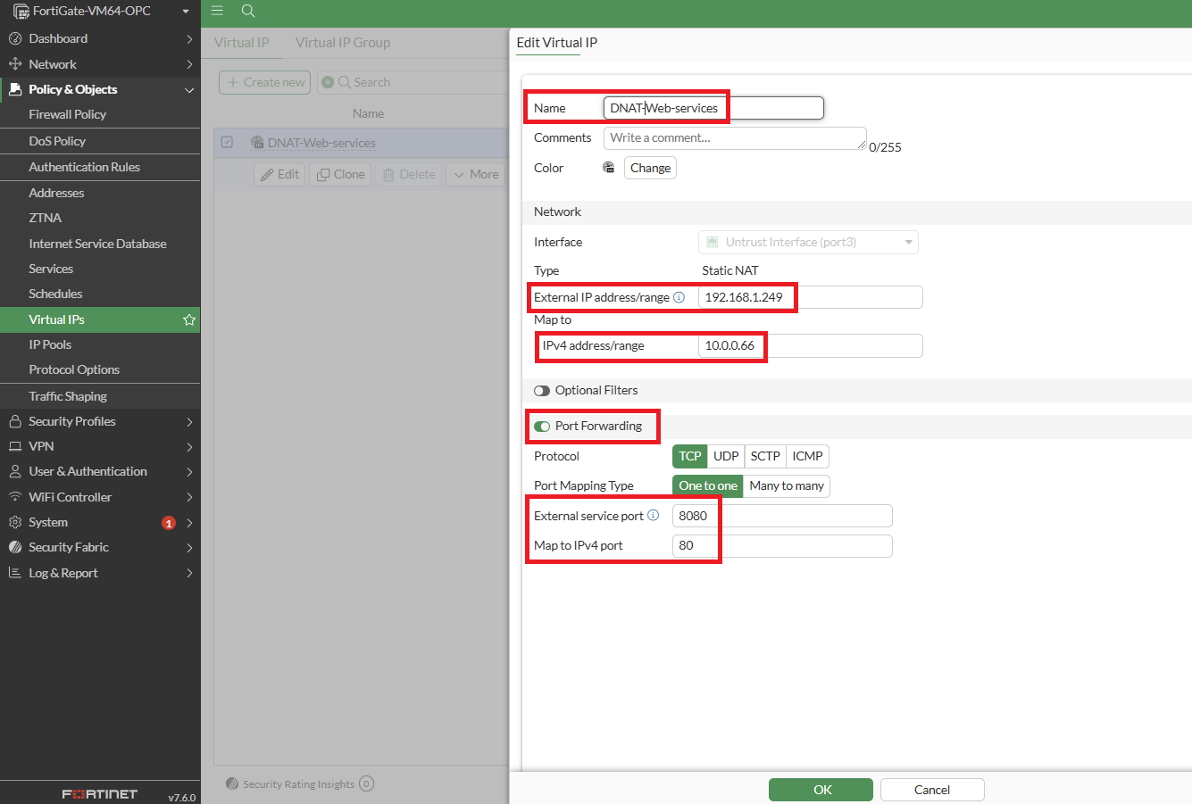
Step 4: Configure a Virtual IP using IP address of Untrust Interface. A virtual IP (VIP) maps external IP addresses to internal IP addresses for DNAT.
In this setup, the untrust interface IP (192.168.1.249) is mapped to the Load Balancer IP (10.0.0.66) located in the Spoke1 VCN. Port forwarding is enabled to allow external clients to access the web services.
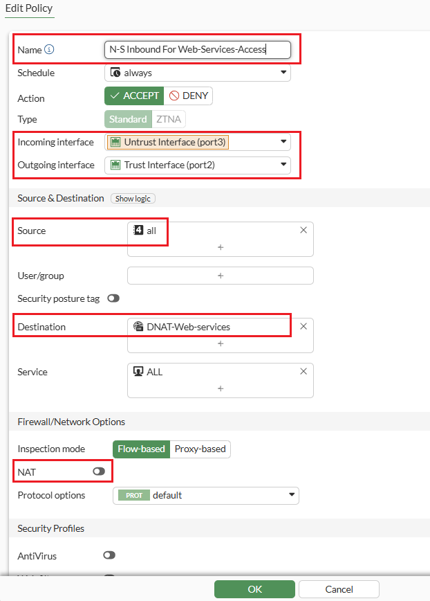
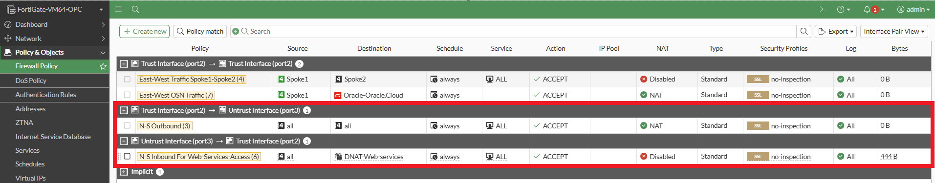
Step 5: Expand the ‘Policy and Objects’ from left-side panel and click on ‘Firewall Policy’ to create the “N-S Inbound for Web-Services-Access” policy which permits inbound traffic to flow from the Untrust to the Trust interface. It utilizes the destination address specified in the D-NAT rule configured in (Step 4) to route the traffic to the Load Balancer.
Below is the detailed overview of the Firewall Policy configuration for “N-S Inbound for Web Services Access” proceed with the configuration steps as outlined.
Step 6: Configure the “N-S Outbound” policy as shown below which enables outbound traffic to flow from the Trust interface to the Untrust interface. It utilizes the Internet Gateway to reach the internet, with S-NAT enabled.
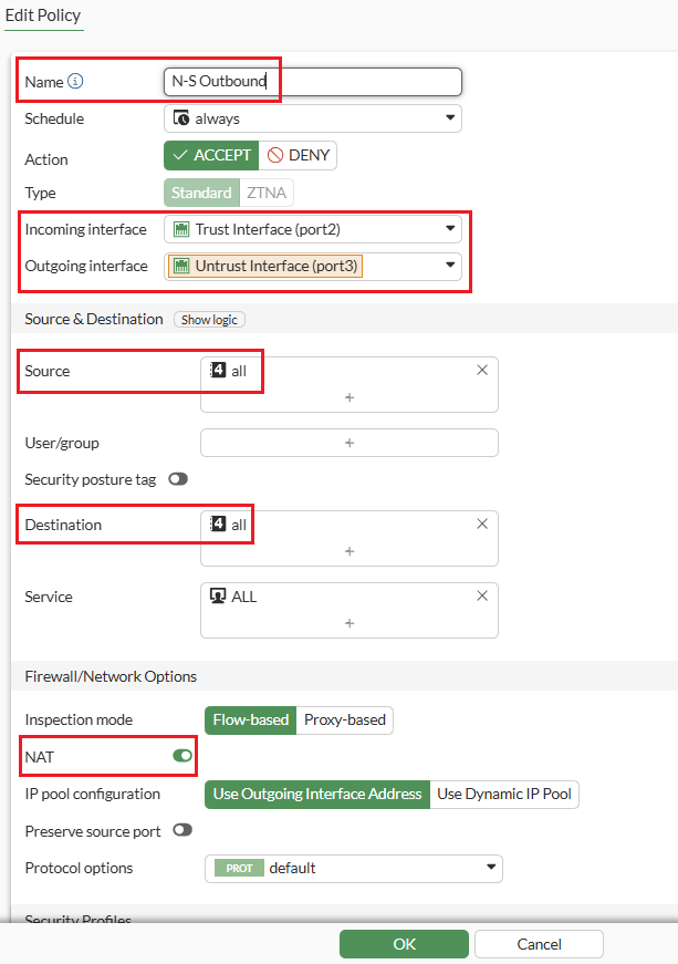
The focus is specifically on N-S policies, so we have configured firewall policies for North-South inbound and outbound which looks like below.
Demonstrating use cases:
Usecase1: Inbound traffic inspection for accessing applications hosted in the Spoke1 VCN from the internet and on-premises.
The diagram below shows the step-by-step traffic flow, demonstrating how internet users access the web application hosted on a NGINX server running on a VM. This server is located behind a load balancer in the Spoke1 VCN.
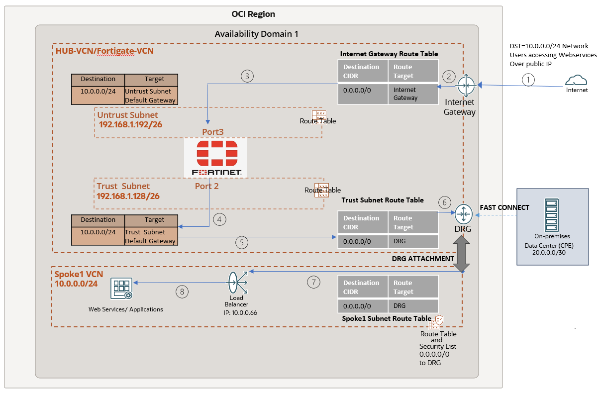
While the above diagram focuses on traffic inbound from the internet, the flow is very similar for traffic initiated from your on-prem datacenters. Instead of passing through the Internet Gateway, the traffic will route through the DRG and enter the untrust interface (step 3 above). There onwards it will follow the same path.
Verification:
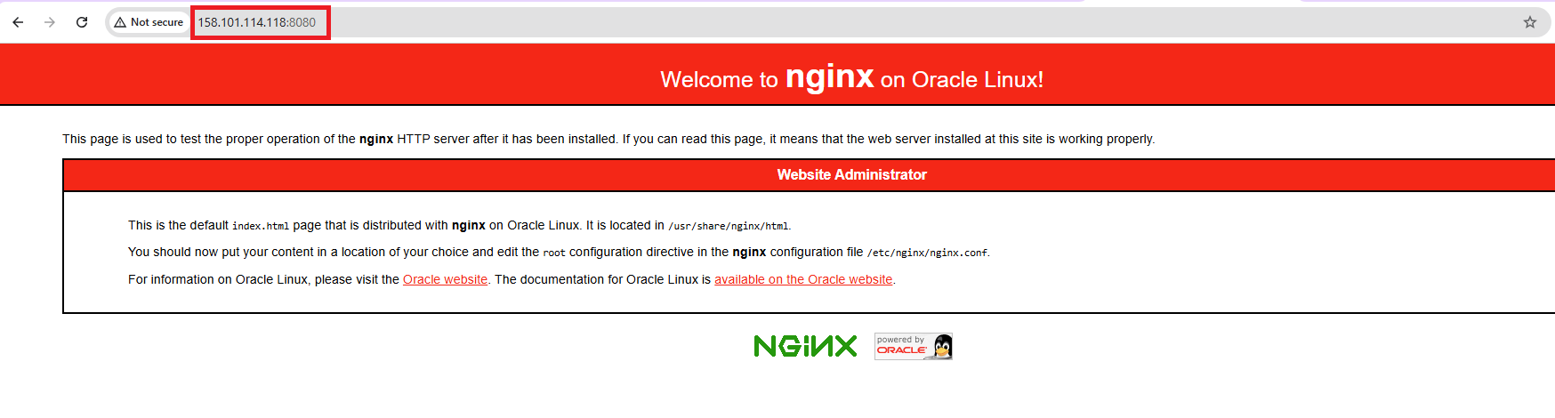
To verify, let’s use a public VM with IP (129.80.102.211) to access the web services through the Untrust interface’s public IP (158.101.114.118) on port 8080. This will display the default NGINX page.
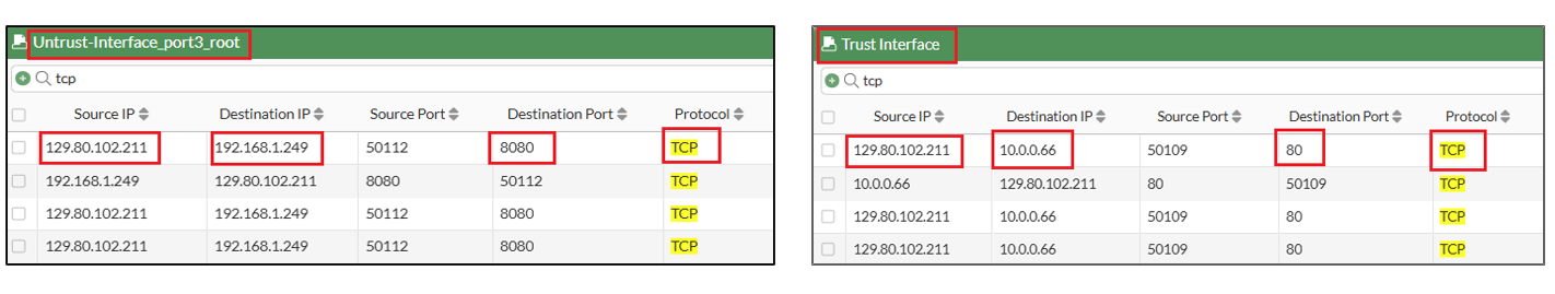
In the capture on the Untrust and Trust interfaces, we observe traffic from the user (129.80.102.211) first reaching the Untrust interface and then proceeding to the Trust interface using the policy “N-S Inbound for Web Services Access”. The destination IPs are as follows:
- Untrust interface: 192.168.1.249
- Load Balancer (LB): 10.0.0.66
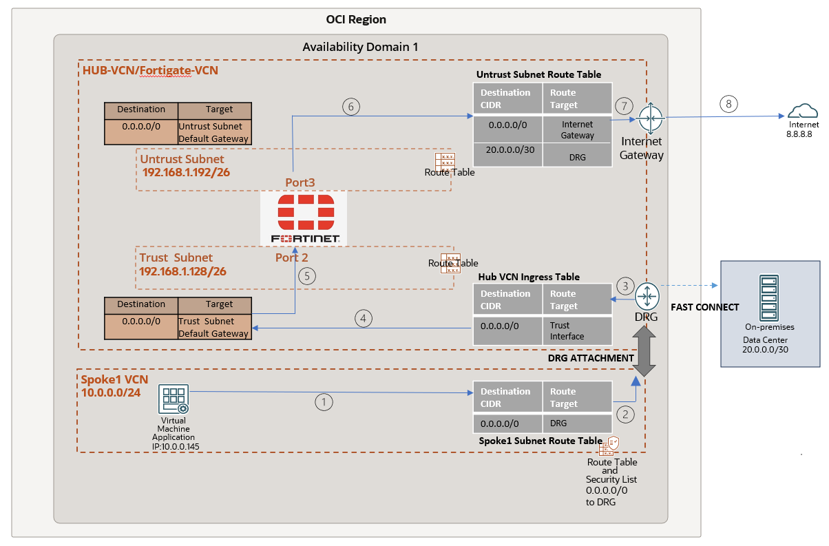
Usecase2: Outbound traffic inspection for Spoke VMs to access the internet and on-premises.
This diagram shows the step-by-step traffic flow when VM IP(10.0.0.145) in SPOKE1 VCN access Google DNS IP (8.8.8.8).
Verification:
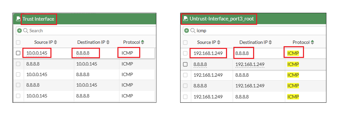
To verify the traffic flow, I initiated a ping to the destination IP 8.8.8.8, using the VM with IP 10.0.0.145 in the Spoke1 VCN as the source. We notice that the traffic first hits the trust interface (IP:192.168.1.178) and then routed to untrust (IP 192.168.1.249) interface using the policy “N-S Outbound”.
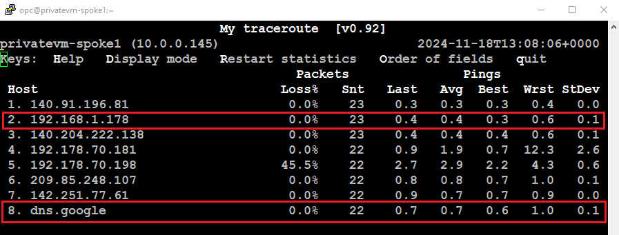
The MTR output from the Spoke1 VM IP (10.0.0.145) shows the Trust interface IP (192.168.1.178) and the destination as Google’s DNS.
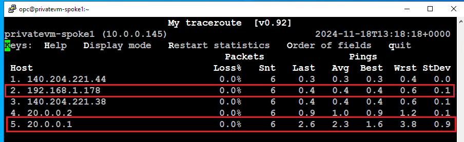
Similarly, to verify the traffic flow to the on-premises network, I initiated a ping to the BGP peer IP (20.0.0.1) located at the customer datacenter. The traffic first reaches the Trust interface and is then routed to the Untrust interface using the “N-S Outbound” policy.
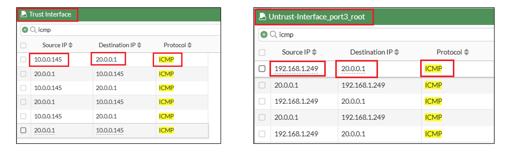
The MTR output from the VM (IP: 10.0.0.145) in Spoke1 VCN shows the Trust interface IP (192.168.1.178) and the destination IP (20.0.0.1).