Introduction
In this blog, I will discuss configuring the Equinix side to connect two Oracle Cloud Infrastructure (OCI) Regions using Equinix Infrastructure. This solution can replace the OCI Remote Peering Connection (RPC) and offers all the benefits of Equinix SLAs.
Please go here for the main page.
Please go here for the OCI side configuration, which is the first part of this blog series.
Please go here for the Equinix side configuration, which is the second part of the blog.
For this connectivity model, we will use:
– Two FastConnects with Equinix as a Partner
– One Equinix Network Edge Device
– Two Equinix Connections
– The Equinix Fabric infrastructure.
In this blog, we will use the following technologies:
– Equinix Palo Alto VM-Series Firewall https://docs.equinix.com/en-us/Content/Interconnection/NE/deploy-guide/PaloAlto/NE-migration-PAN-firewall.htm
– Equinix Network EDGE Virtual Device – for more information, please access official documentation at https://docs.equinix.com/en-us/Content/Interconnection/NE/user-guide/NE-create-device.htm
– Palo Alto VM-Series Deployment guide https://docs.paloaltonetworks.com/vm-series/9-1/vm-series-deployment
– Palo Alto Pan-OS 10.2 or later Advanced Routing https://docs.paloaltonetworks.com/pan-os/10-2/pan-os-networking-admin/advanced-routing
Prerequisites
In this blog, we will cover how to provision Equinix infrastructure. To do this, we will need the following resources already provisioned and configured:
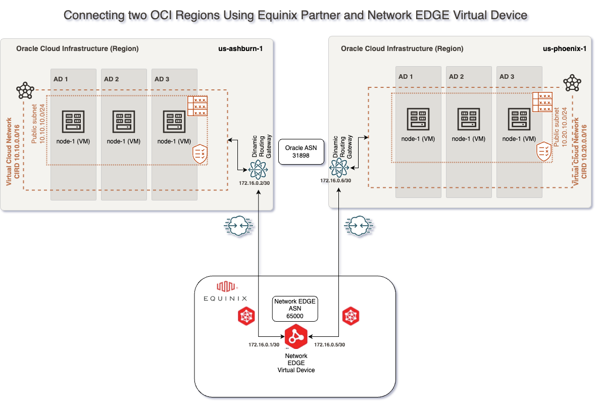
1. VCNs – in our case, we will have a VCN in the Ashburn region with 10.10.0.0/16 CIDR and another VCN in the Phoenix region with 10.20.0.0/16 CIDR with all routing and Security List / Network Security Groups to allow connectivity between Ashburn and Phoenix CIDR Blocks
2. 2 DRGs – in our case, one DRG in Ashburn and one DRG in Phoenix with VCN attachments and routing in place to allow traffic between Ashburn VCN and Phoenix VCN
3. 2 Compute VMs – in our case, one compute VM in Ashburn with IP 10.10.10.193 and one in Phoenix with IP 10.20.10.165
4. Access to the Equinixportal with the possibility to provision and Order required components.
5. Prepare and have all the needed data handy to configure this solution. In our case, what I have prepared is:
# Ashburn VCN CIDR = 10.10.0.0/16
# Ashburn subnet = 10.10.10.0/24
# Ashburn Compute instance IP = 10.10.10.193
# Ashburn Fastconnect BGP subnet = 172.16.0.0/30
# Phoenix VCN CIDR = 10.20.0.0/16
# Phoenix subnet = 10.20.10.0/24
# Phoenix Compute instance IP = 10.20.10.165
# Phoenix Fastconnect BGP subnet = 172.16.0.4/30
# EquinixBGP ASN = 133937
# Oracle BGP ASN = 31898
Solution Description
This solution does not focus on redundancy or on how to configure Securities Policies on the Network Edge Virtual Device, and the connectivity will be based on this network diagram:
This blog will focus on how we can configure the Palo Alto VM-Series Network Edge Virtual Device, which can be done by following the following steps:
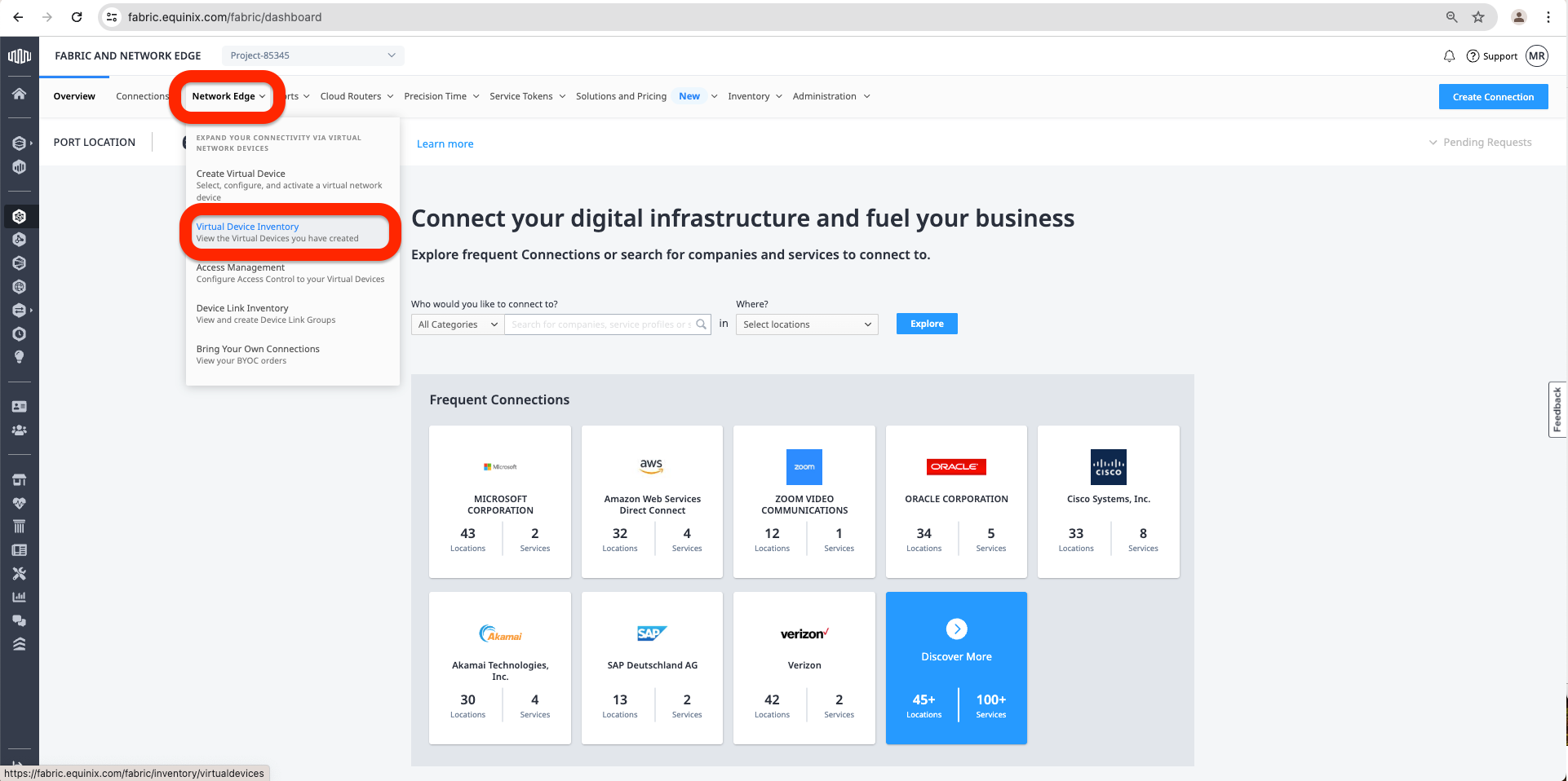
a. Access the Equinix Fabric at https://fabric.equinix.com/. Log in with your credentials, go to the Network Edge tab, and click Virtual Device Inventory.
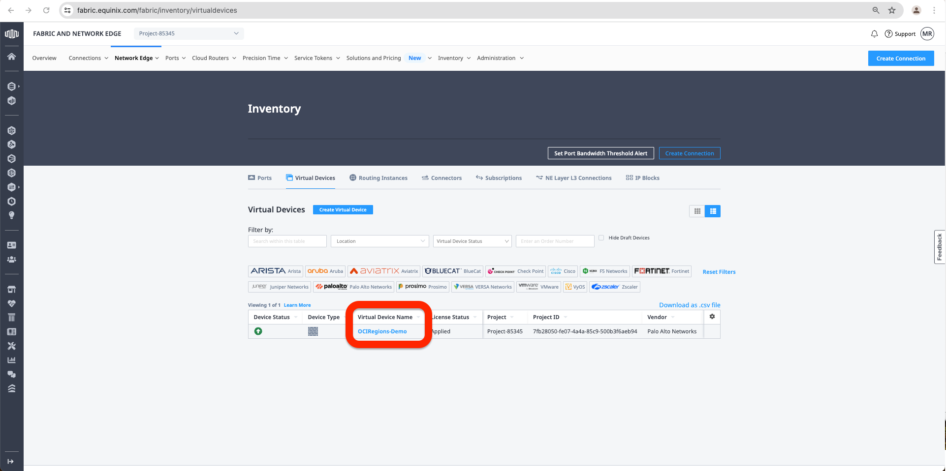
b. Select the network device by clicking on the Virtual Device Name.
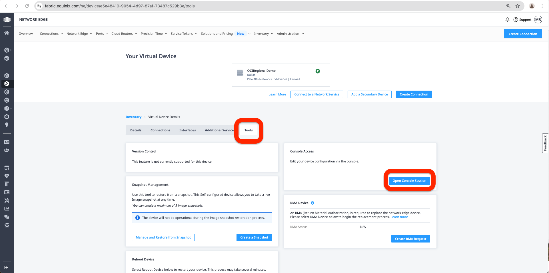
c. First, we must go to the Tools Tab and click Open Console Connection.
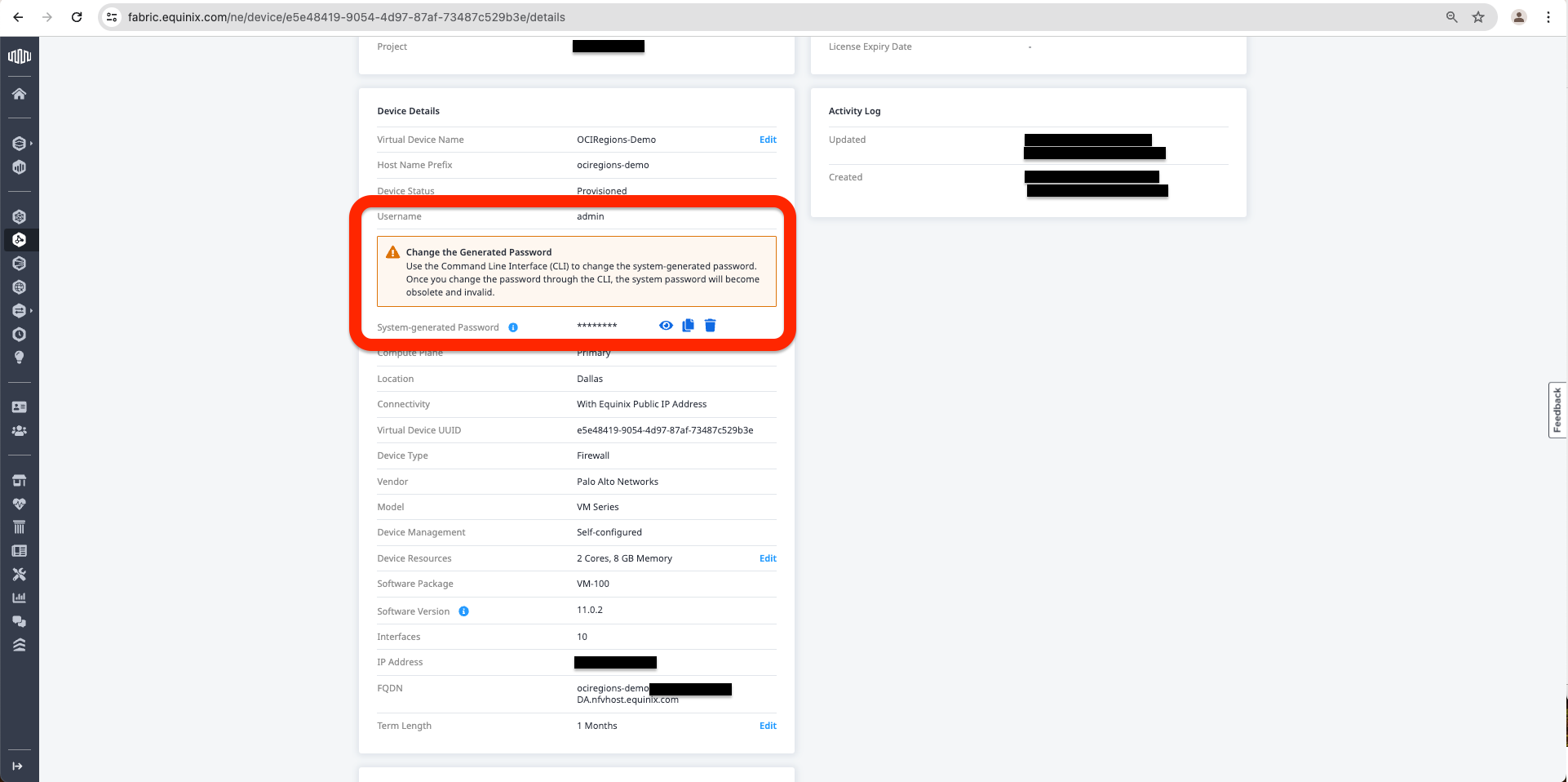
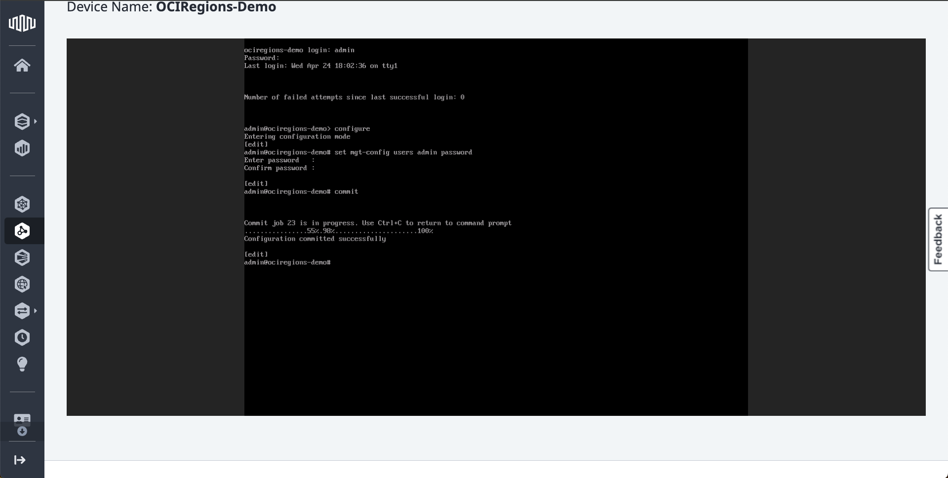
d. On the console connection, we need to change the initial Password provided by Equinix in the Virtual Device under the Details Tab. To change the password, we need to use the following commands after we are logged on to the Virtual Device Console:
- “configure”.
- “set mgt-config users admin password”.
- Type in the New Password.
- Confirm the New Password.
- “commit”.
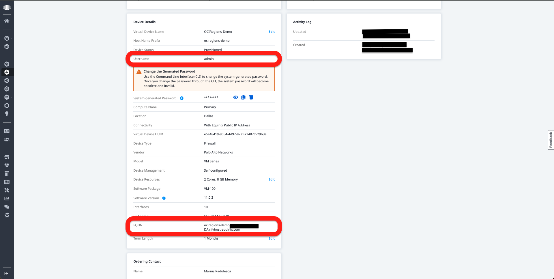
e. Now we can use details from the Details tab:
- The FQDN to connect to Palo Alto VM GUI.
- The username was chosen at the creation of the Network Edge Device.
- The New Password was created in the previous step.
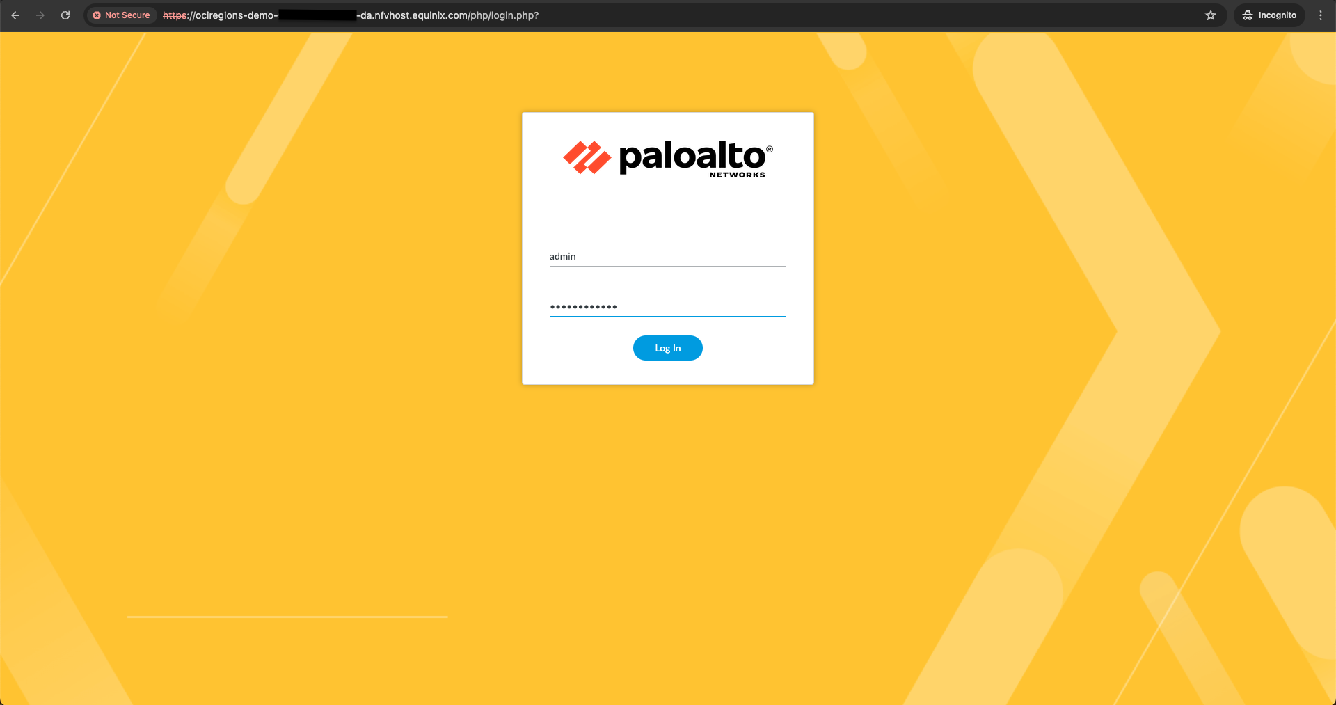
To connect to Palo Alto GUI.
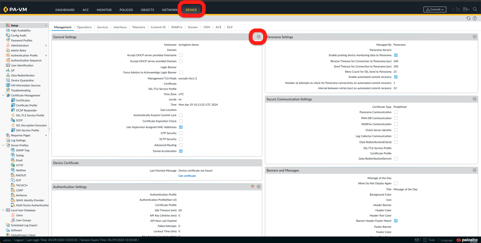
f. Once I am logged in to the Palo Alto, please read through and close the Welcome Message and all other messages; I need to activate the Advance Routing options by going to the Device Tab and clicking on the Gear icon under General Settings.
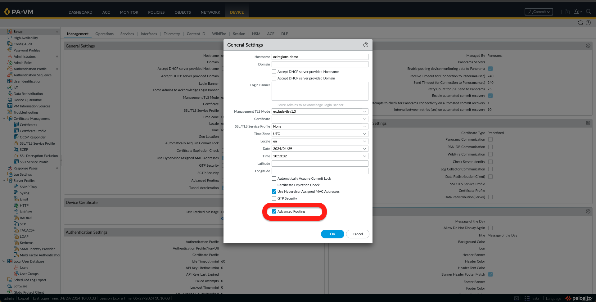
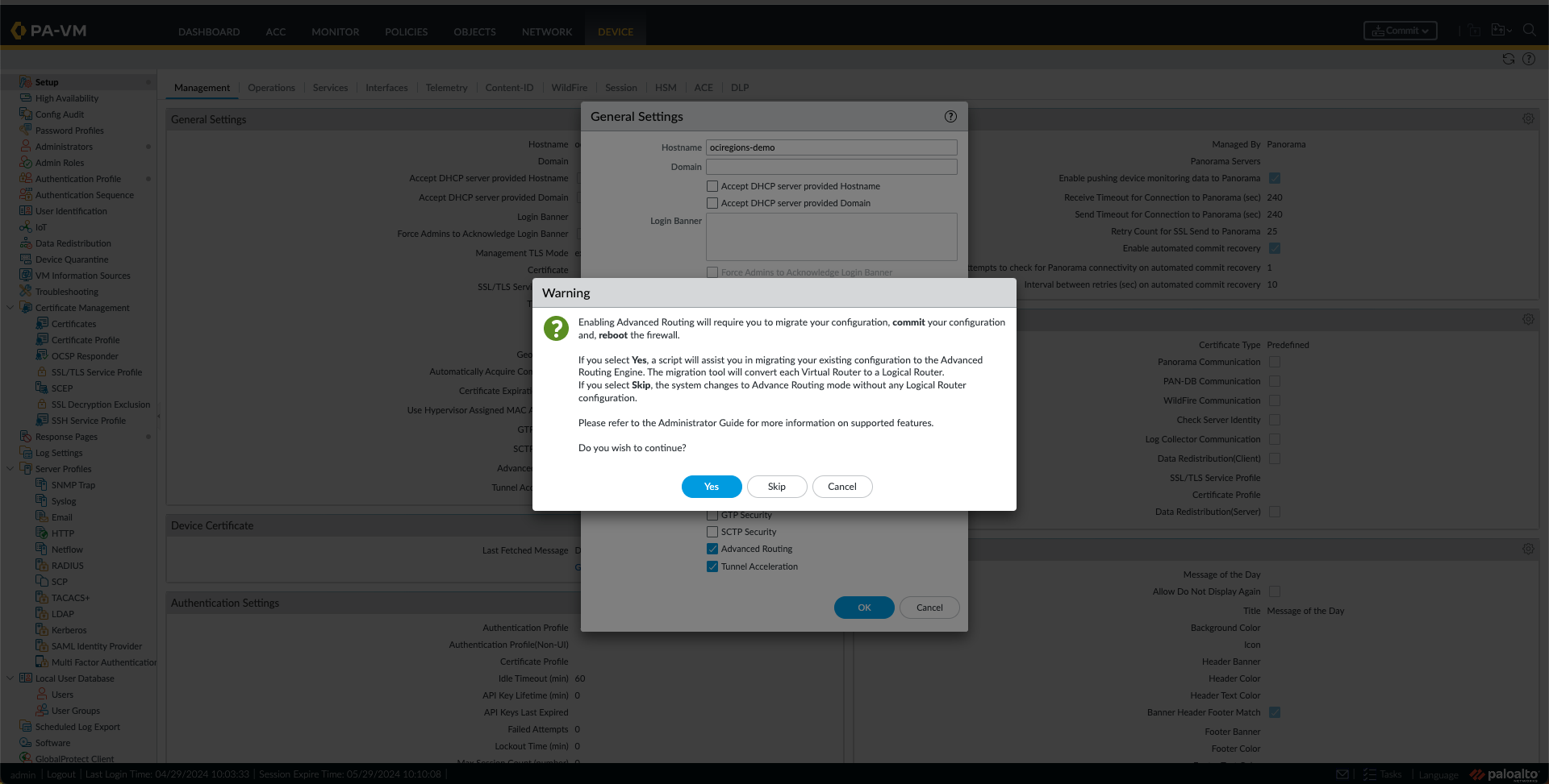
g. Check the Advance Routing Option and click OK. Now, a Warning message will appear. Click on Yes. On the following message, click on OK. Once the next window with Migration appears, click on Continue. The last confirmation regarding activation of the Advance Routing feature appears to select Yes.


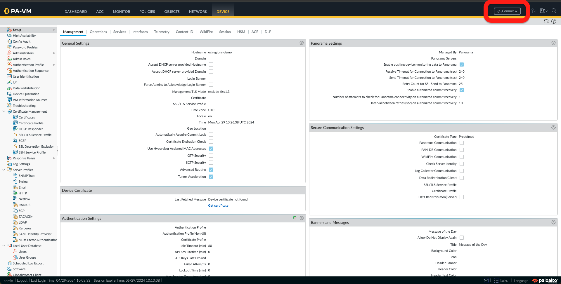
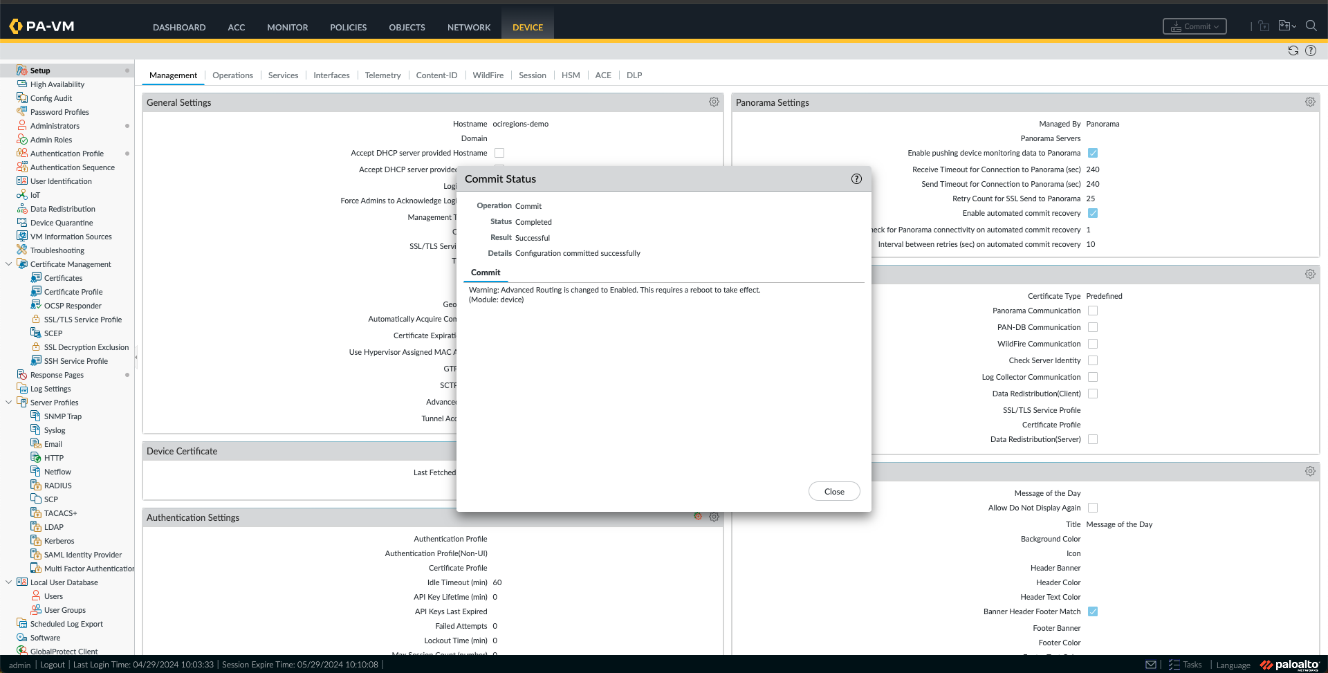
h. All we need now is to commit and reboot the device. First, select the Commit button and click Commit. Once the configuration is committed, we can close the window.
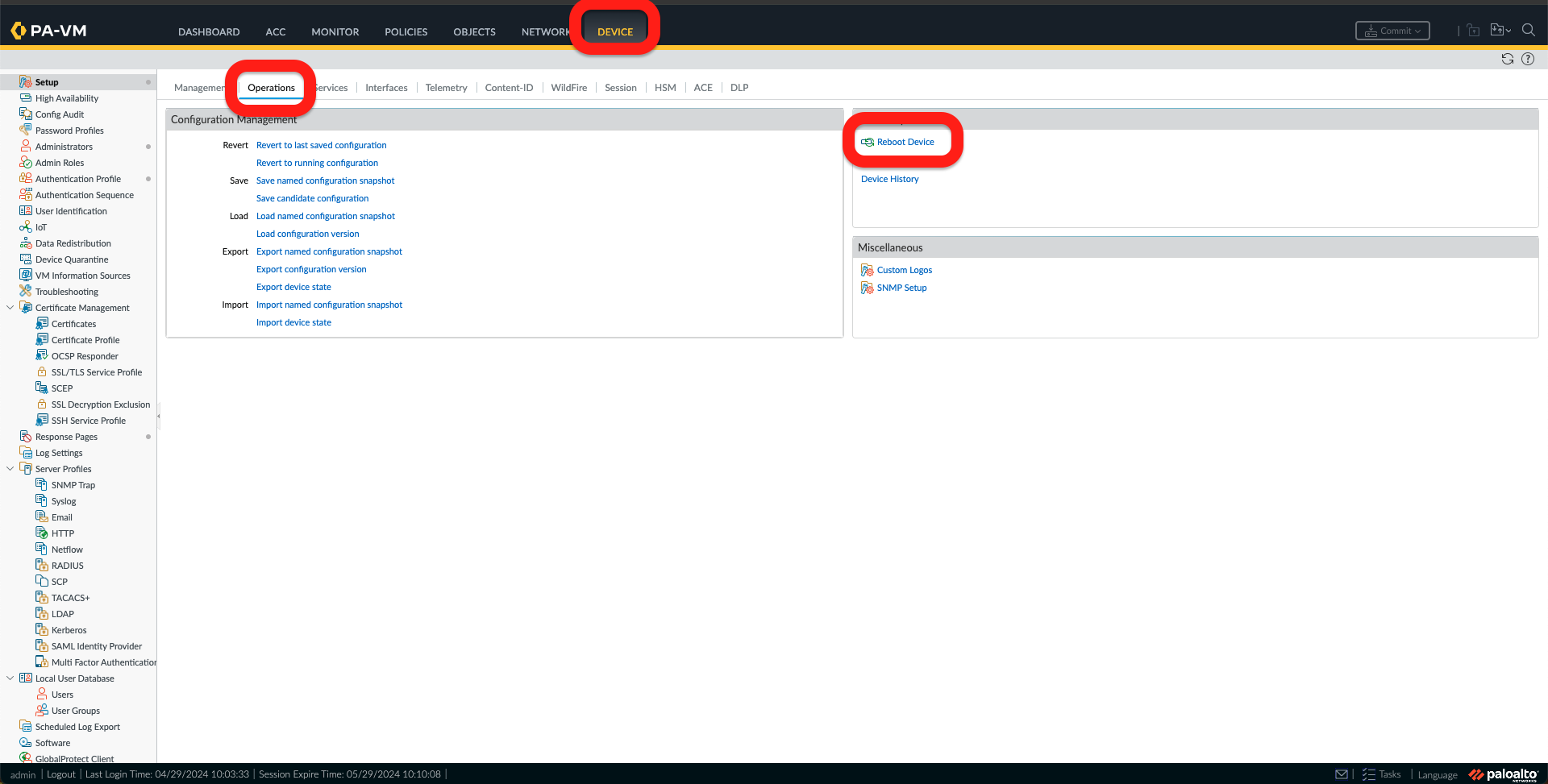
i. Now we need to reboot the Firewall by going to the Device Tab, under Operations, and clicking Reboot Device. Confirm Reboot Device by clicking Yes.

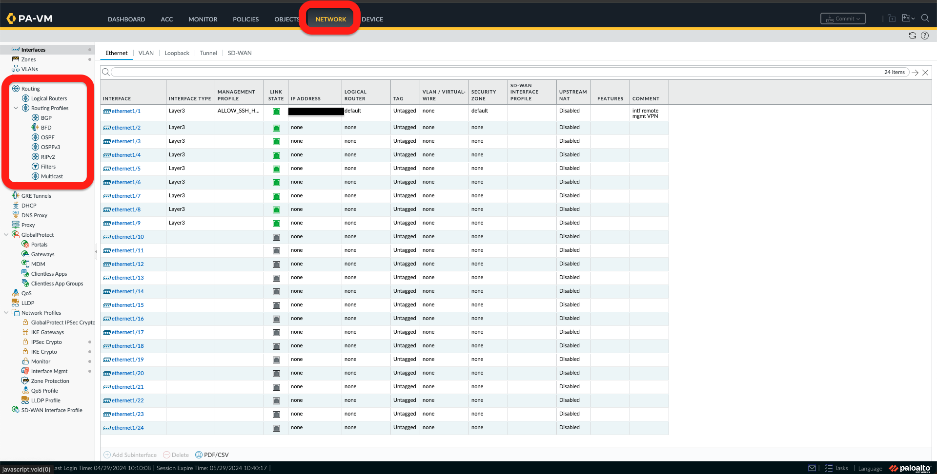
j. Once the device is rebooted, log on again. Under the Network Tab, we should see “Logical Routing” and “Routing Profiles” under Routing, like the picture below.
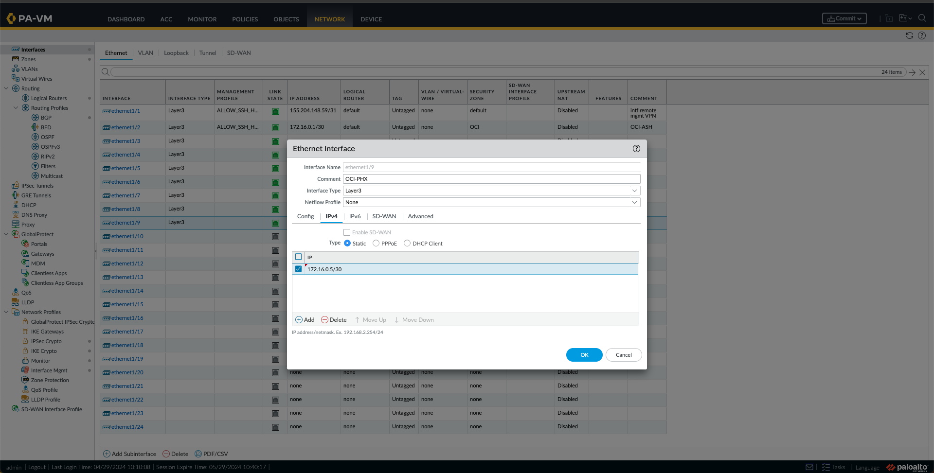
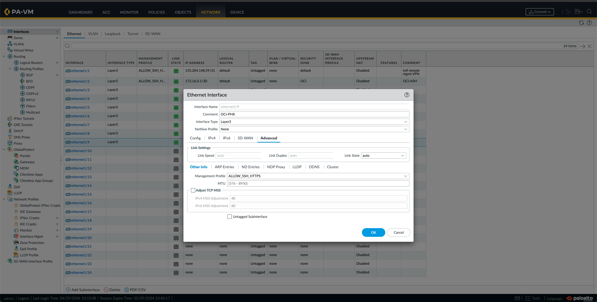
k. Now is the time to configure the Interfaces. First, I will configure the interface “ethernet1/2,” which from the previous blog is the OCI-ASH-FC1 interface, by clicking on it. Provide a Comment. In this case, I used “OCI-ASH,” and under the Config Tab, I selected the Logical Router. The “default” one and a Security Zone were used in this case. In this case, I created a new Zone called “OCI.”Under the IPv4 Tab, I have added the Ashburn BGP IP, in this case, “172.16.0.1/30”. Optionally, I have also added the Management Profile under the Advanced Tab. I clicked OK.


l. I Did the same thing for the Phoenix Interface, In this case, Interface “ethernet1/9”, with the settings and IP from this Connection.
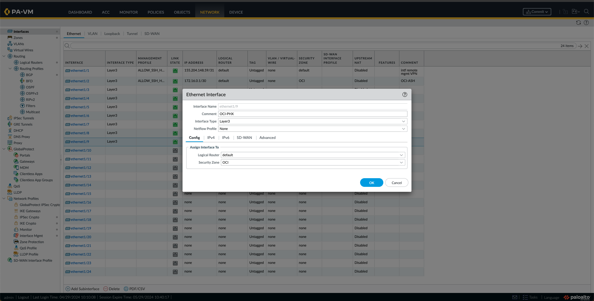
m. At this point, I am seeing the interfaces like this.

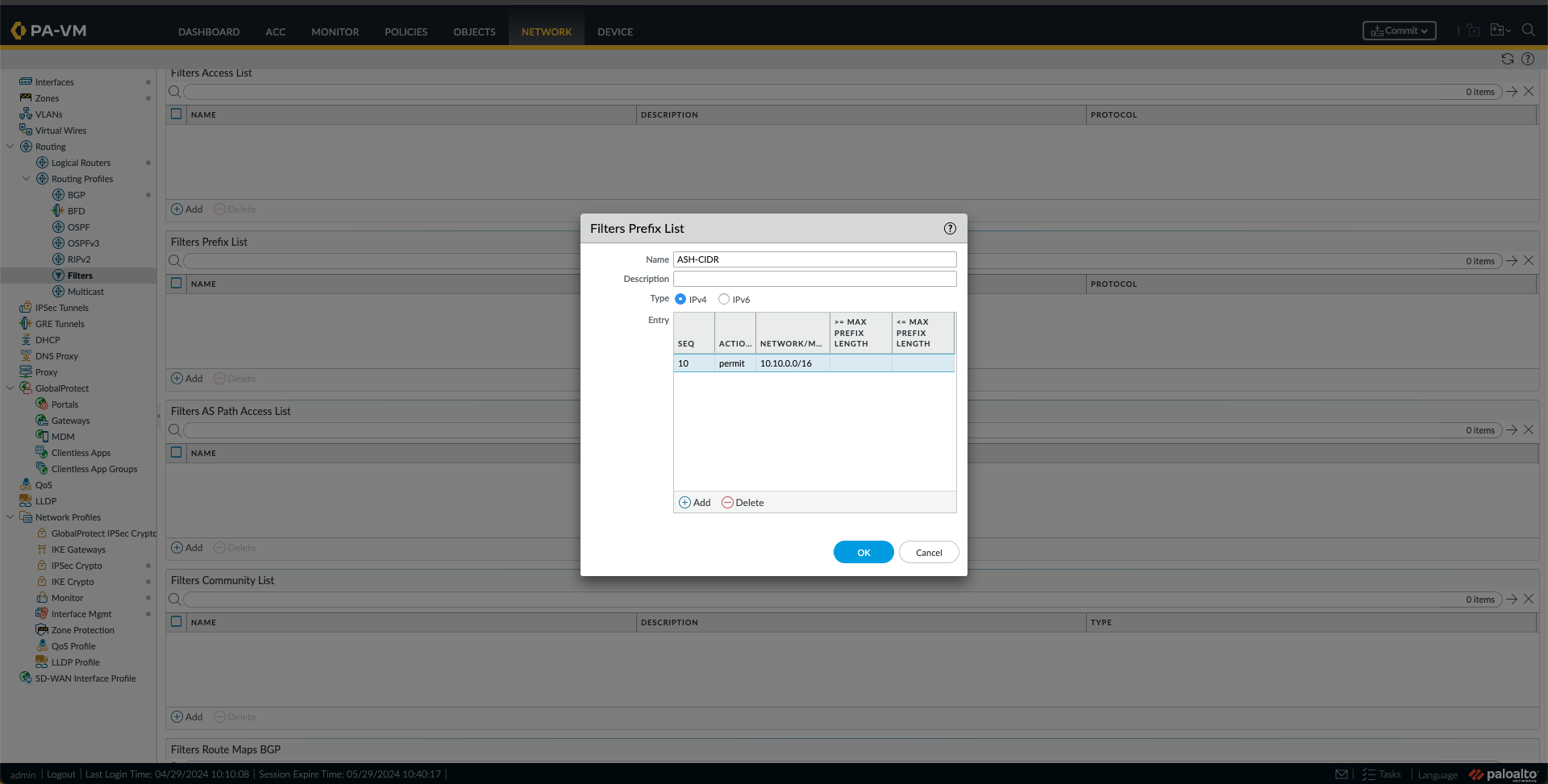
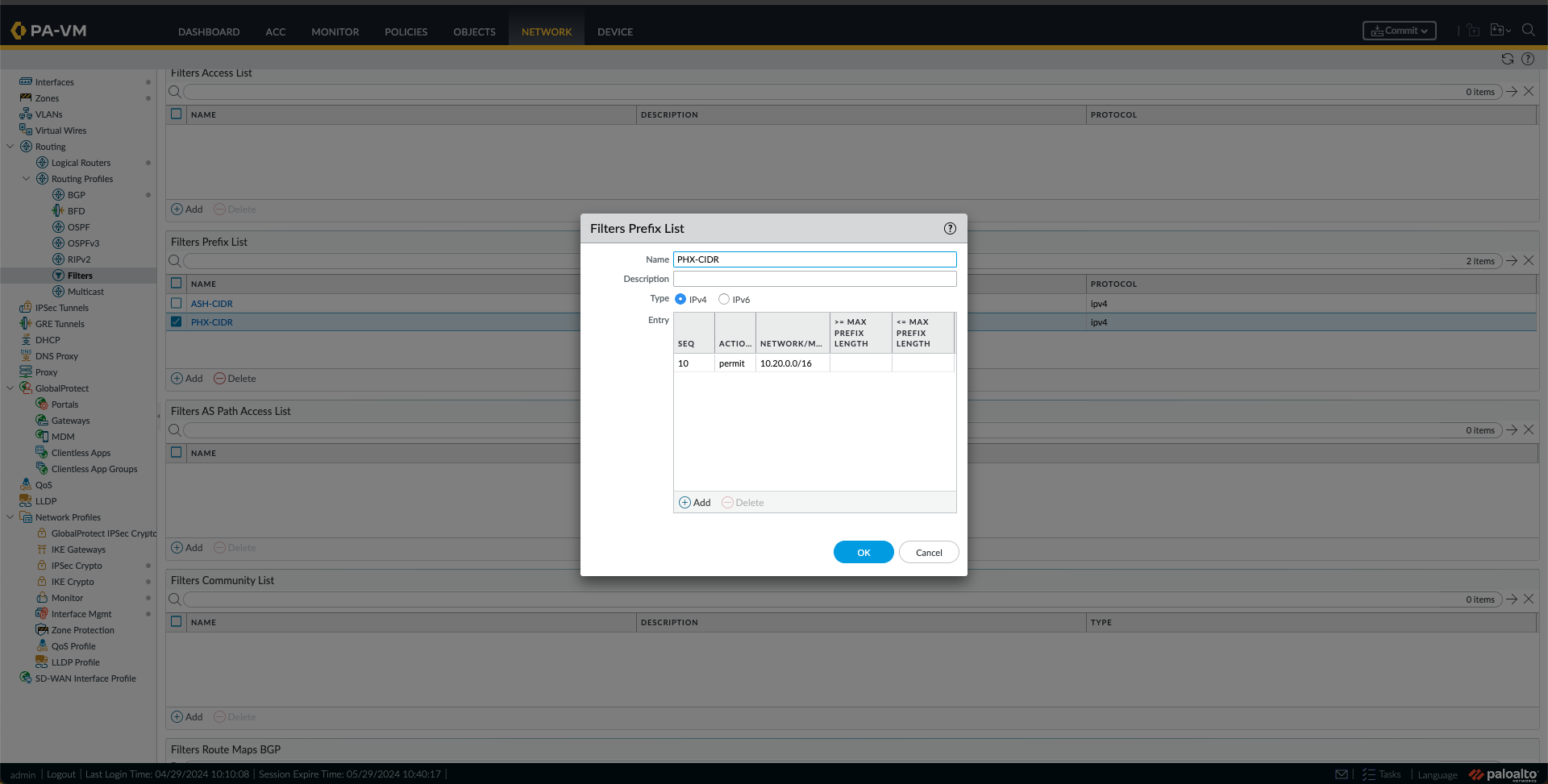
n. Now, I will create some Prefix List Filters by going to Filters under Network, Routing Profiles, and clicking Add under Filters Prefix List. Fill in the Name and create an Entry. First, I did it for Ashburn VCN CIDR; then I made a new prefix list for the Phoenix CIDR. Ultimately, I had two Filters in the Prefix List, as shown below.

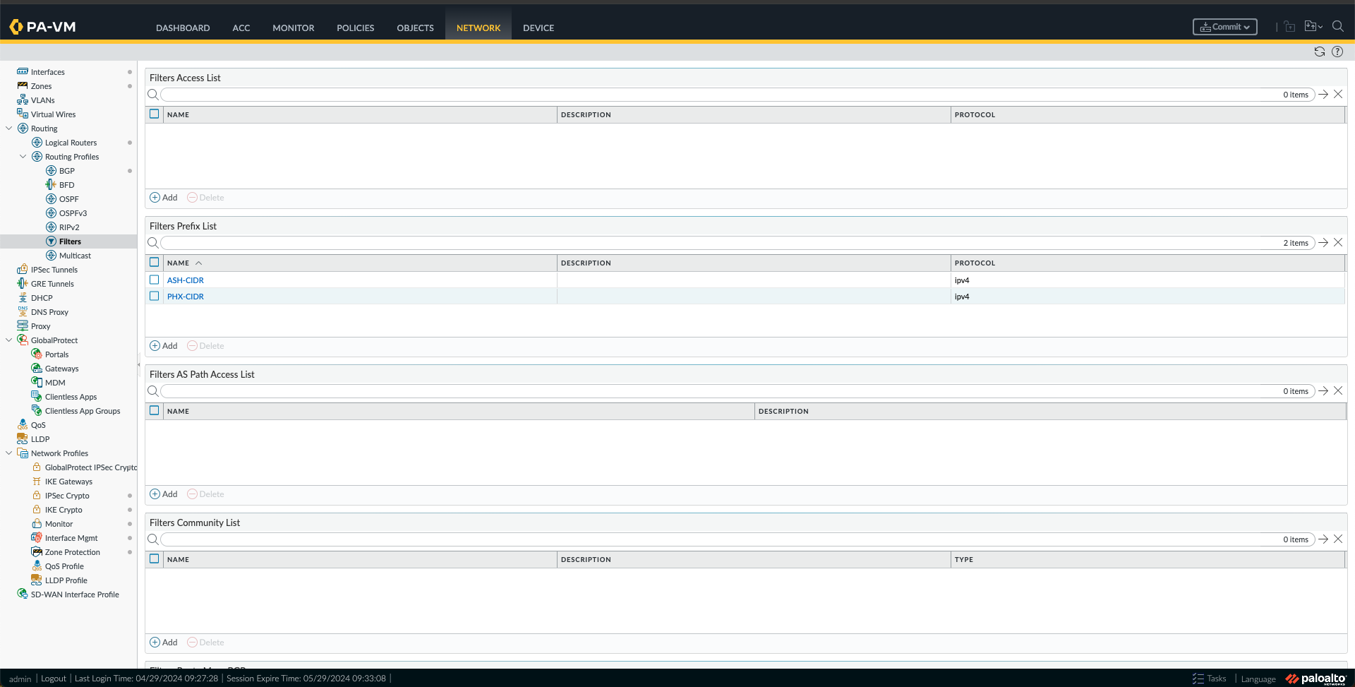
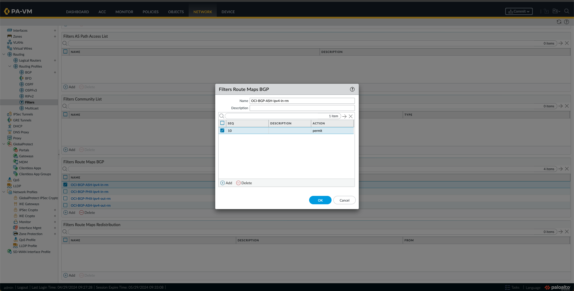
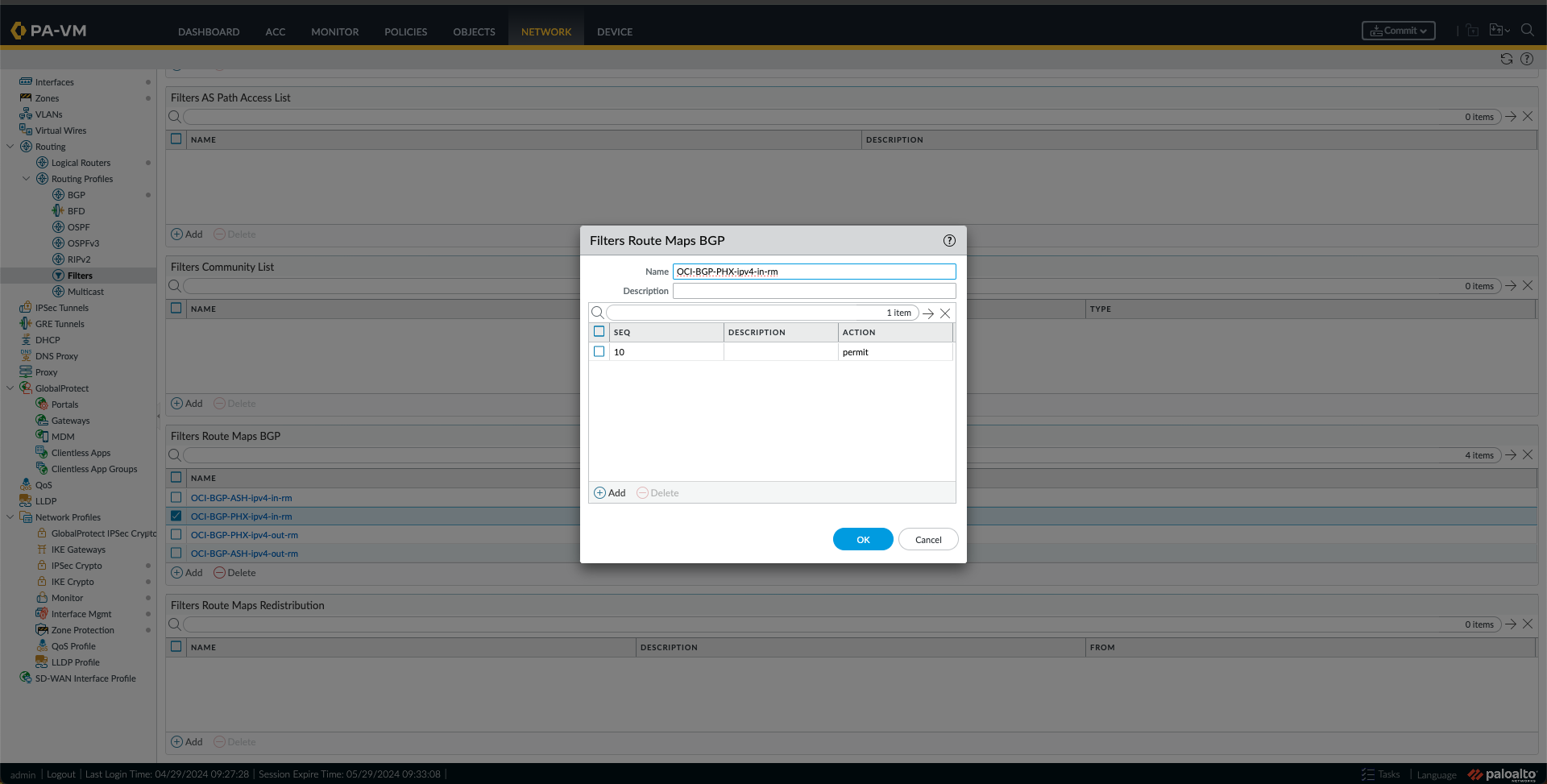
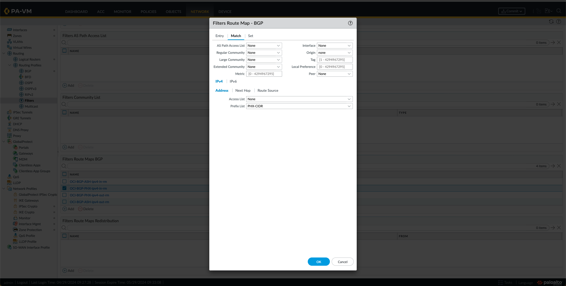
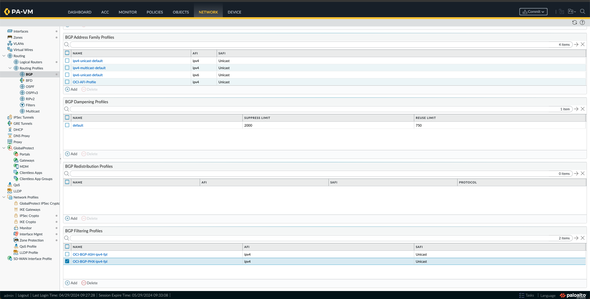
o. Next, I created some Filters Route Maps BGP by going to Filters under Network, Routing Profiles, and clicking Add under Filters Route Maps BGP. I have made four route maps, one route map IN and one route map OUT for each region (ASH and PHX) as follows:
- I created a route map IN for ASH with a match using the ASH-CIDR Prefix List created in the previous step.

- I created a route map IN for PHX with a match using the PHX-CIDR Prefix List created in the previous step.
- I created a route map OUT for ASH with a match using the PHX-CIDR Prefix List created in the previous step.
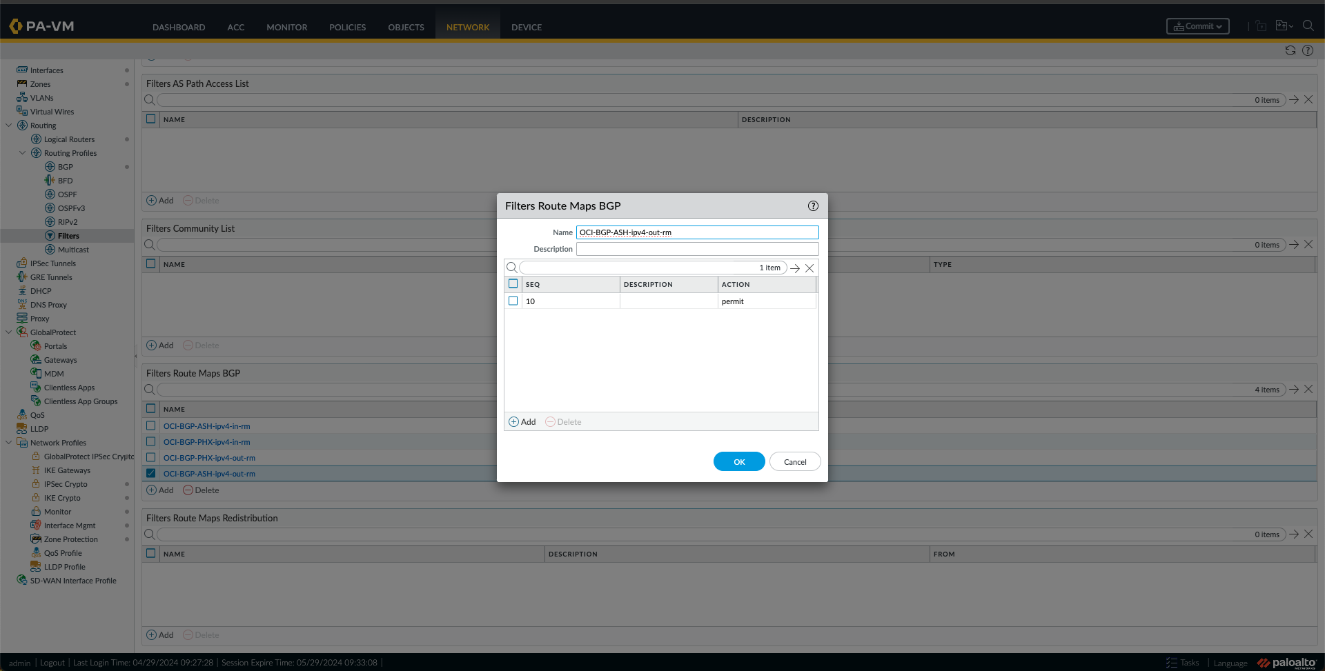
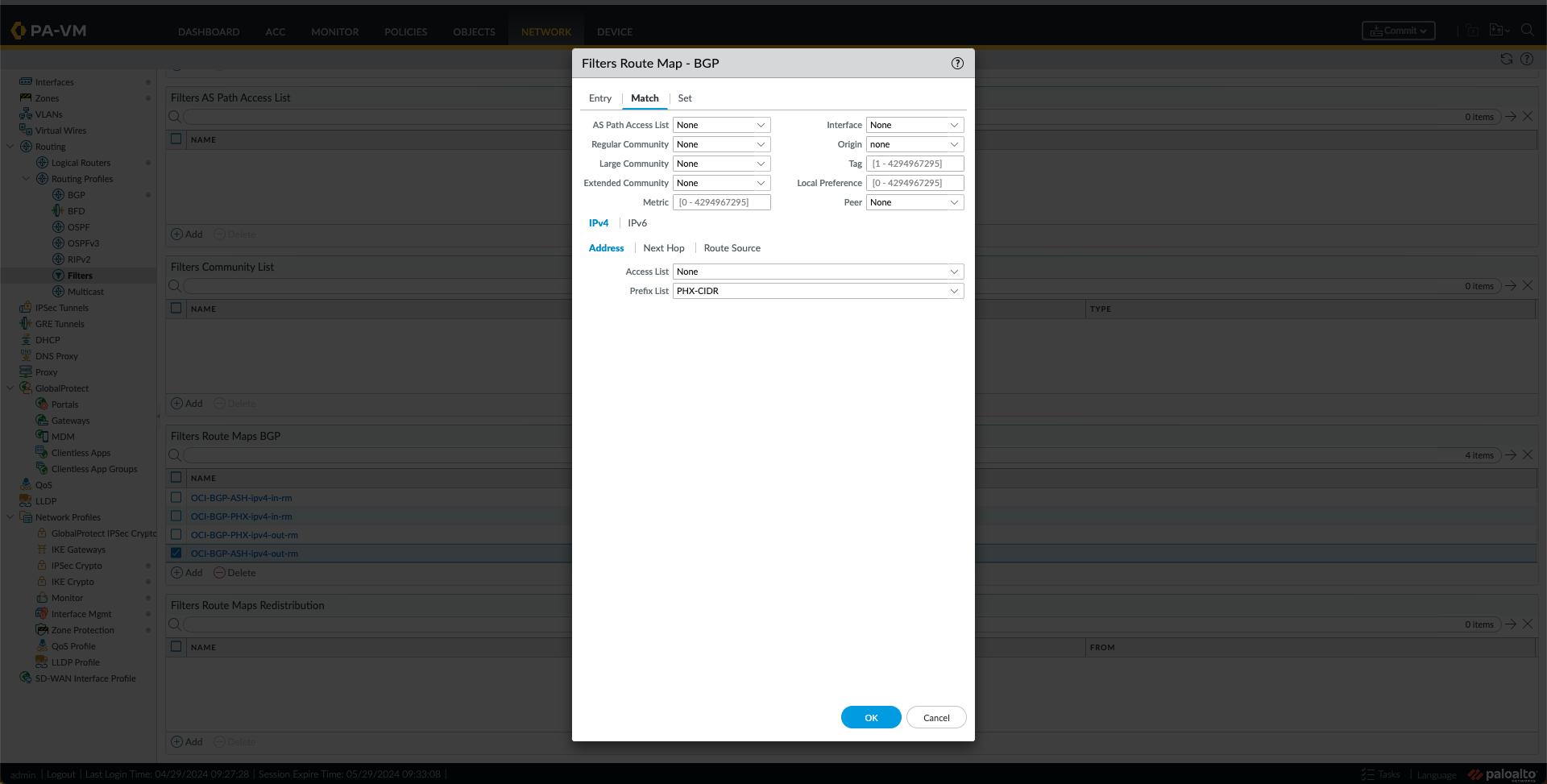
- I created a route map OUT for PHX with a match using the ASH-CIDR Prefix List created in the previous step.


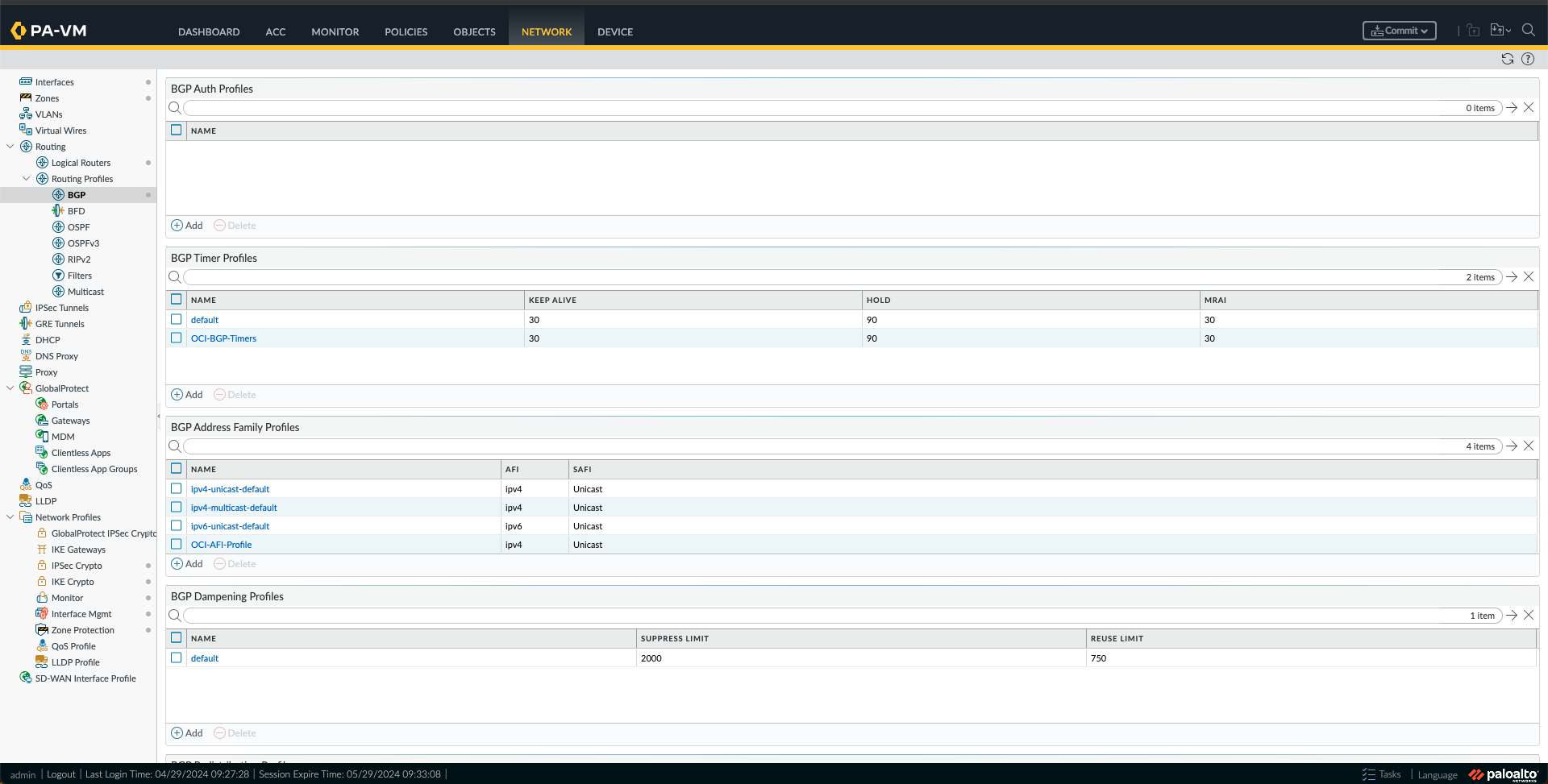
p. Now, under Network -> Routing Profile -> BGP, we need to create the following:

- BGP Filtering Profiles, one for each region using the Route maps created in the previous step.


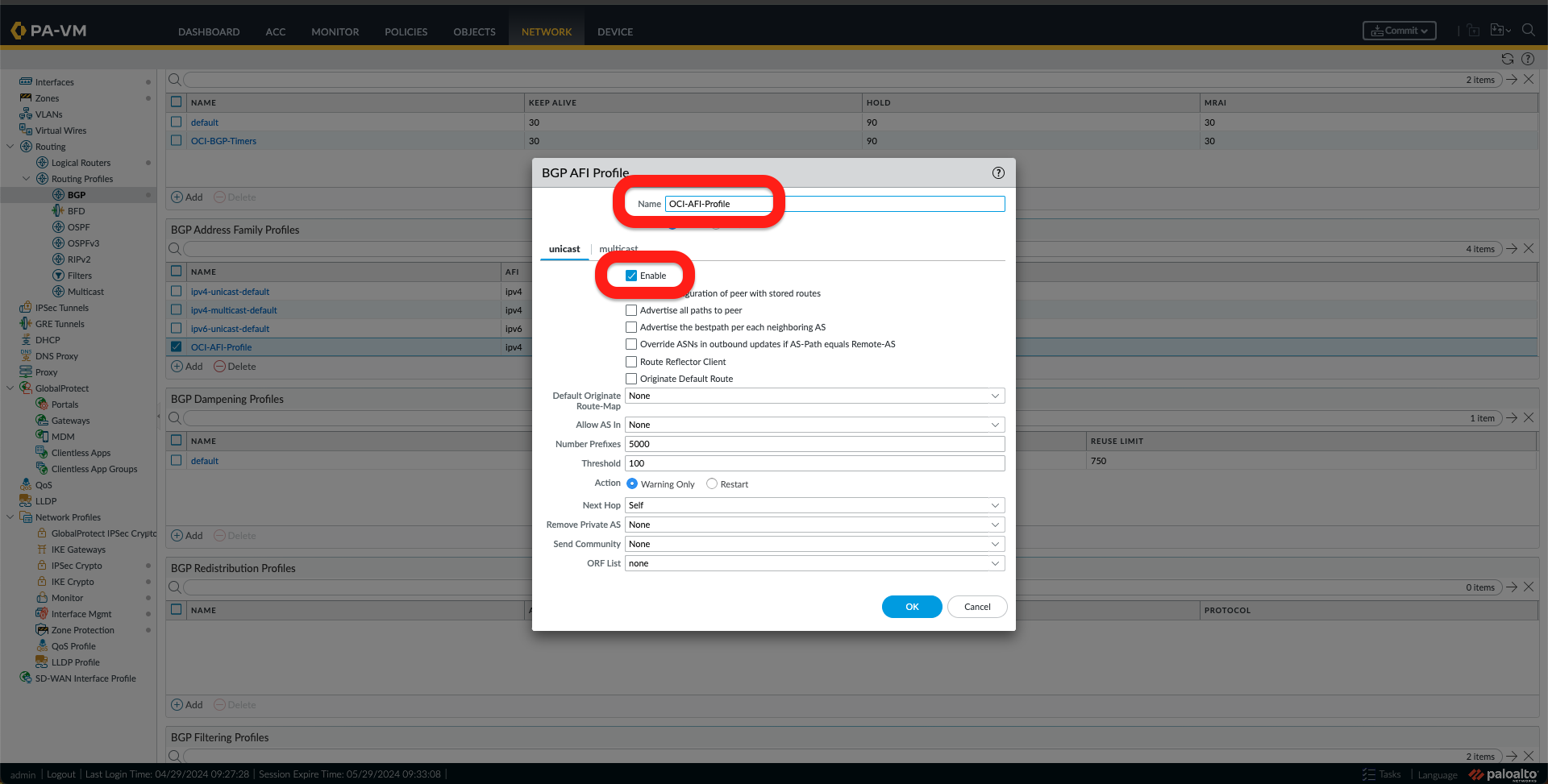
- BGP Address Family Profile, by adding a new profile and activating it.
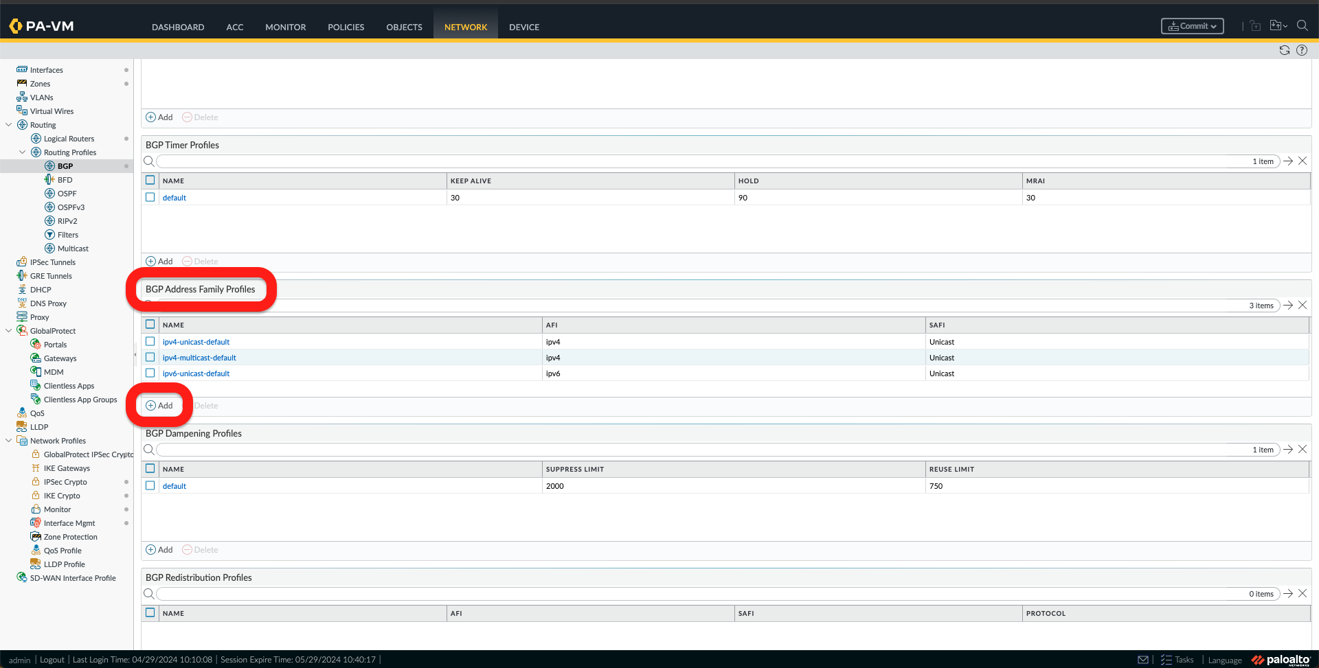
- You can also create BGP Auth Profiles and BGP Times Profiles. I have chosen to create a Timer Profile.
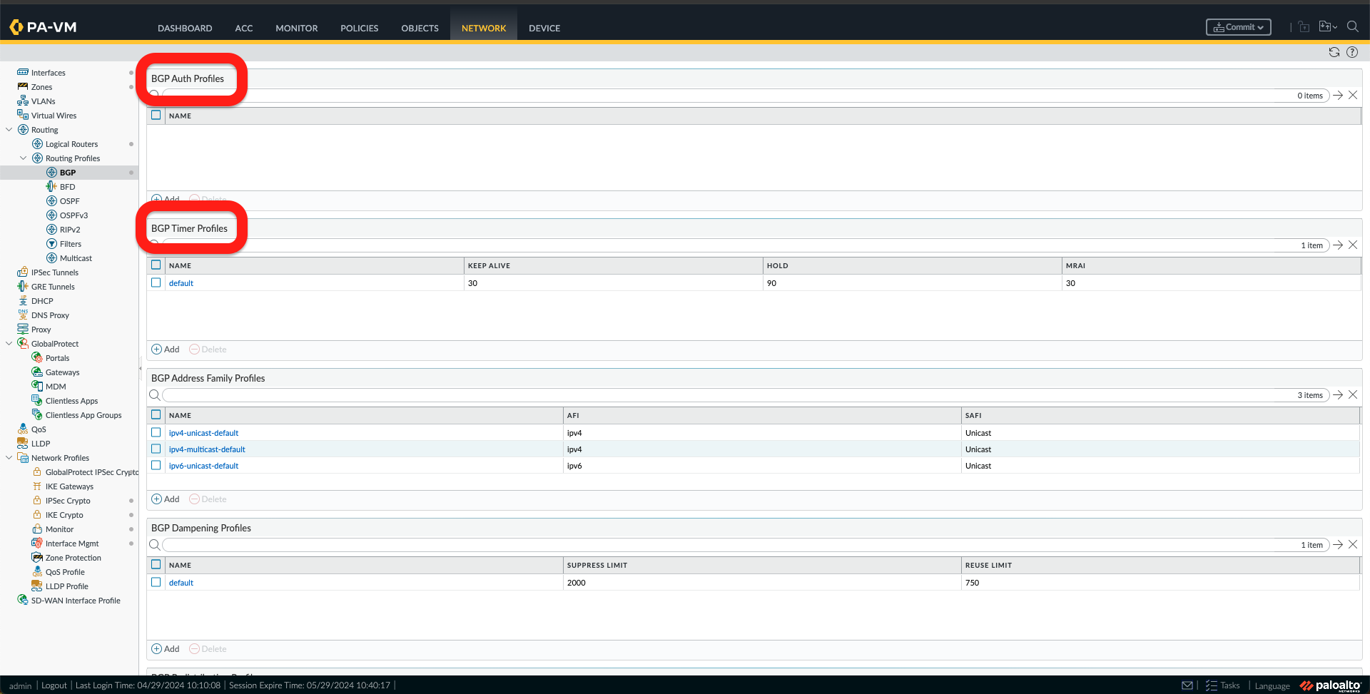
You should have something like this in the images below under Network->Routing Profiles -> BGP.
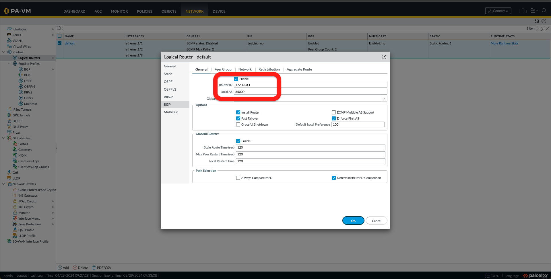
q. The last step of this configuration is to configure BGP. To do this, go to Network -> Logical Routers and click on the logical router name, which, in my case, is the default one. After that, click on BGP.

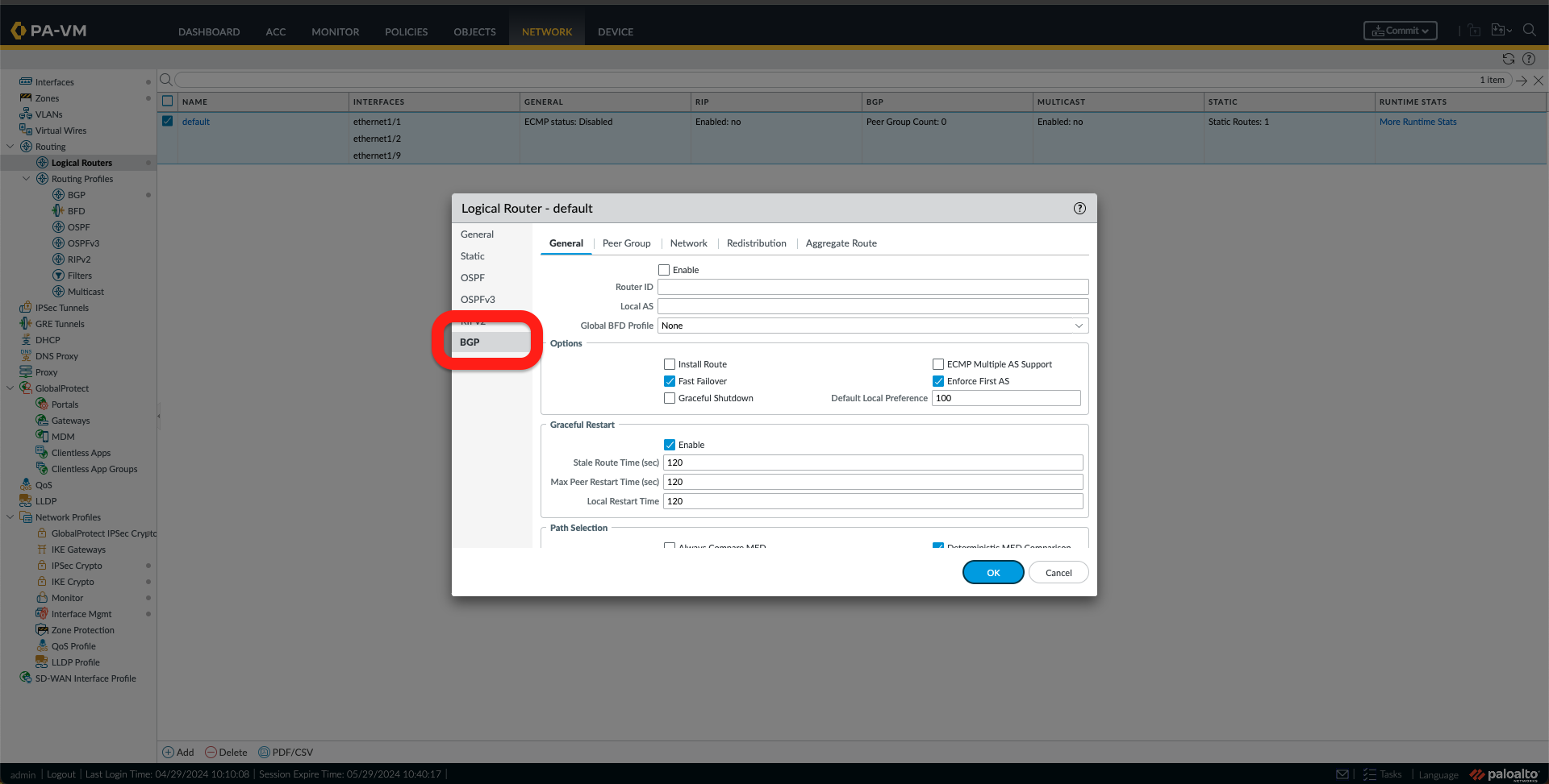
r. Follow the following steps:
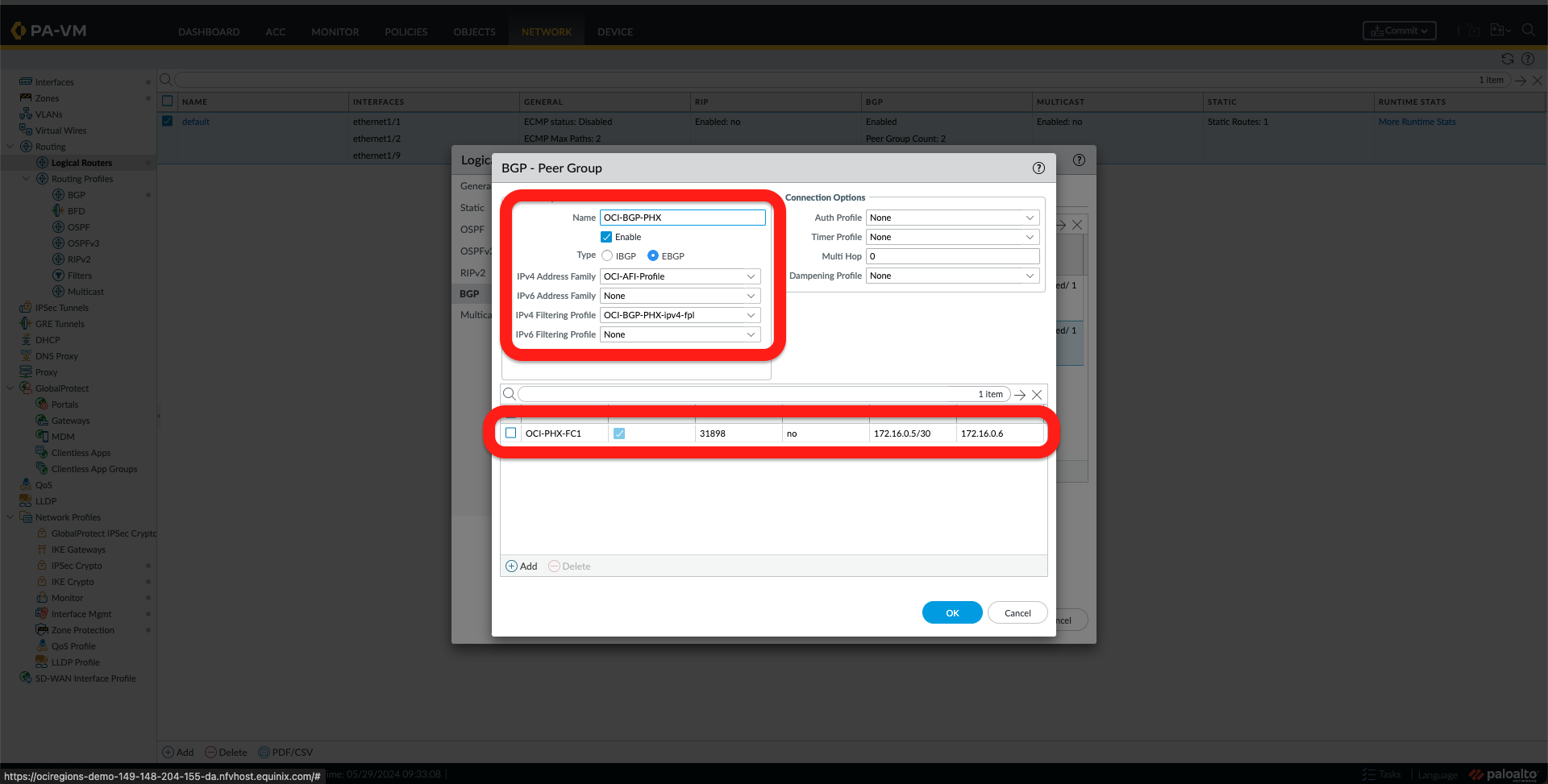
- Select Enable and Add a Router ID and Local AS.
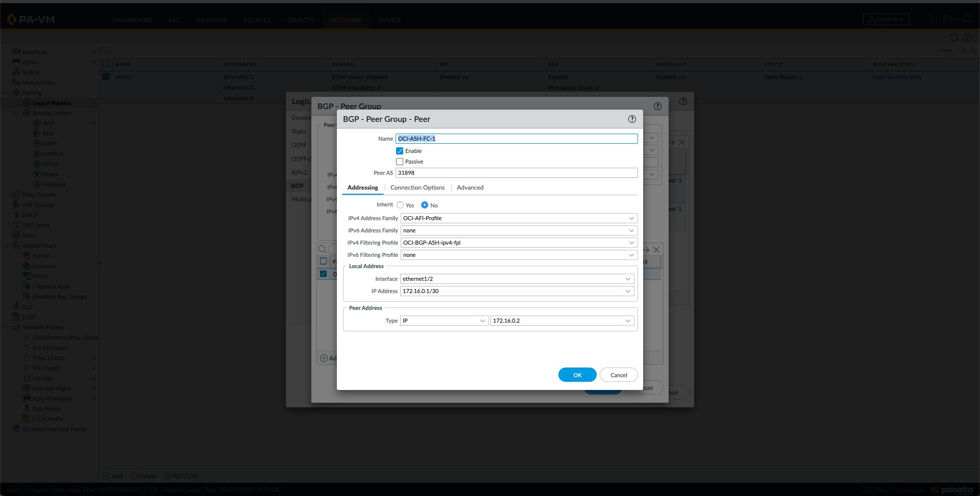
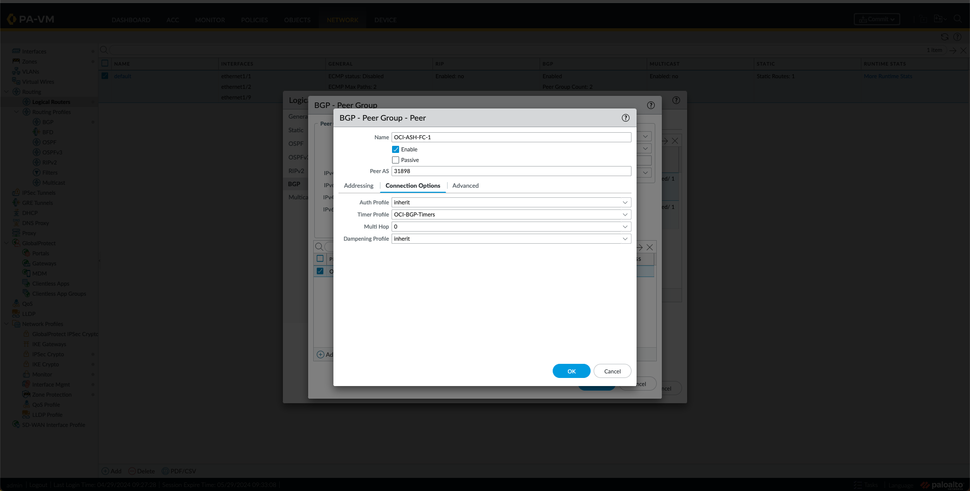
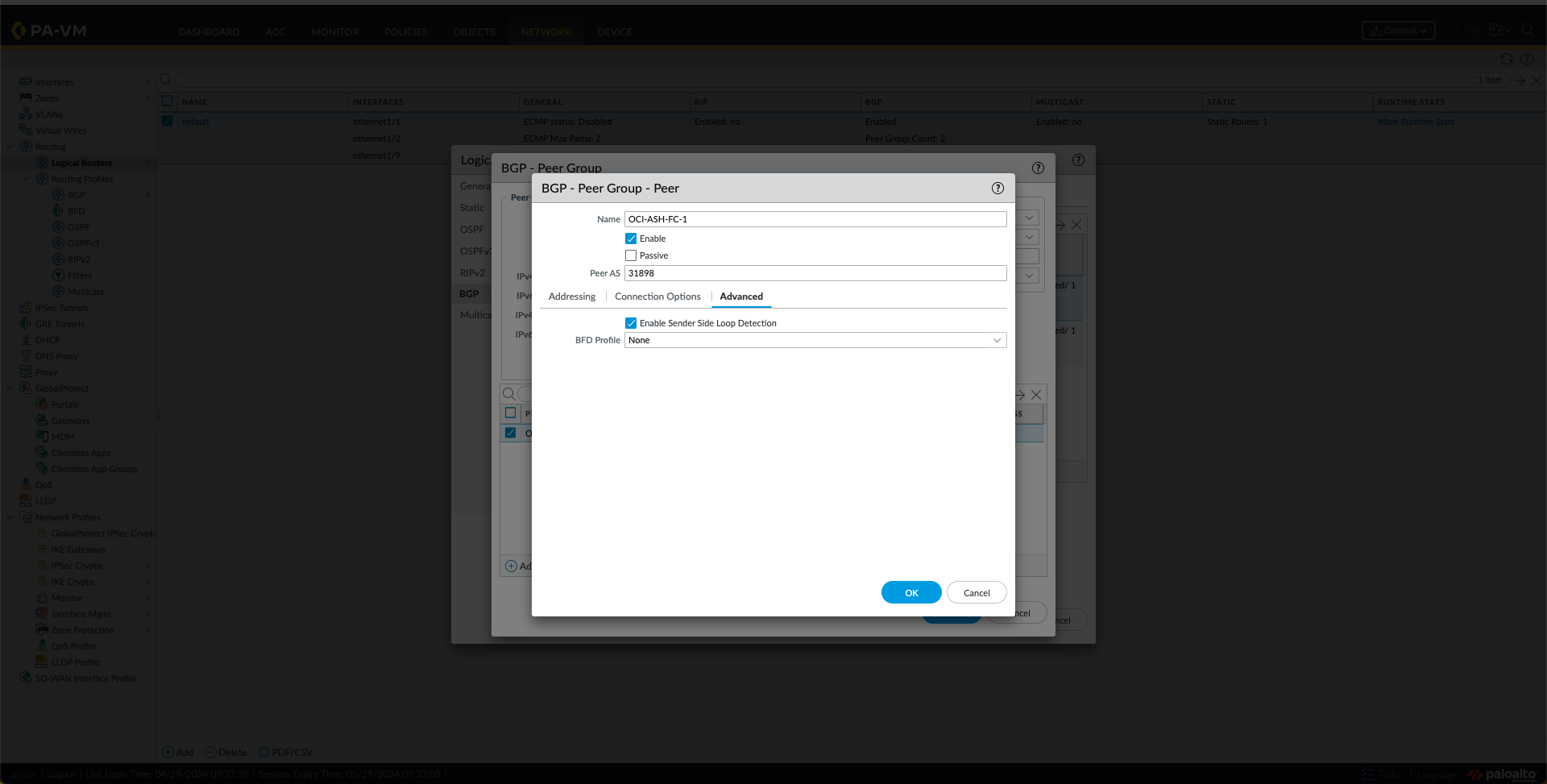
- Under the Peer Group Tab, add two Peers, one for the OCI region, as shown in the following Images.

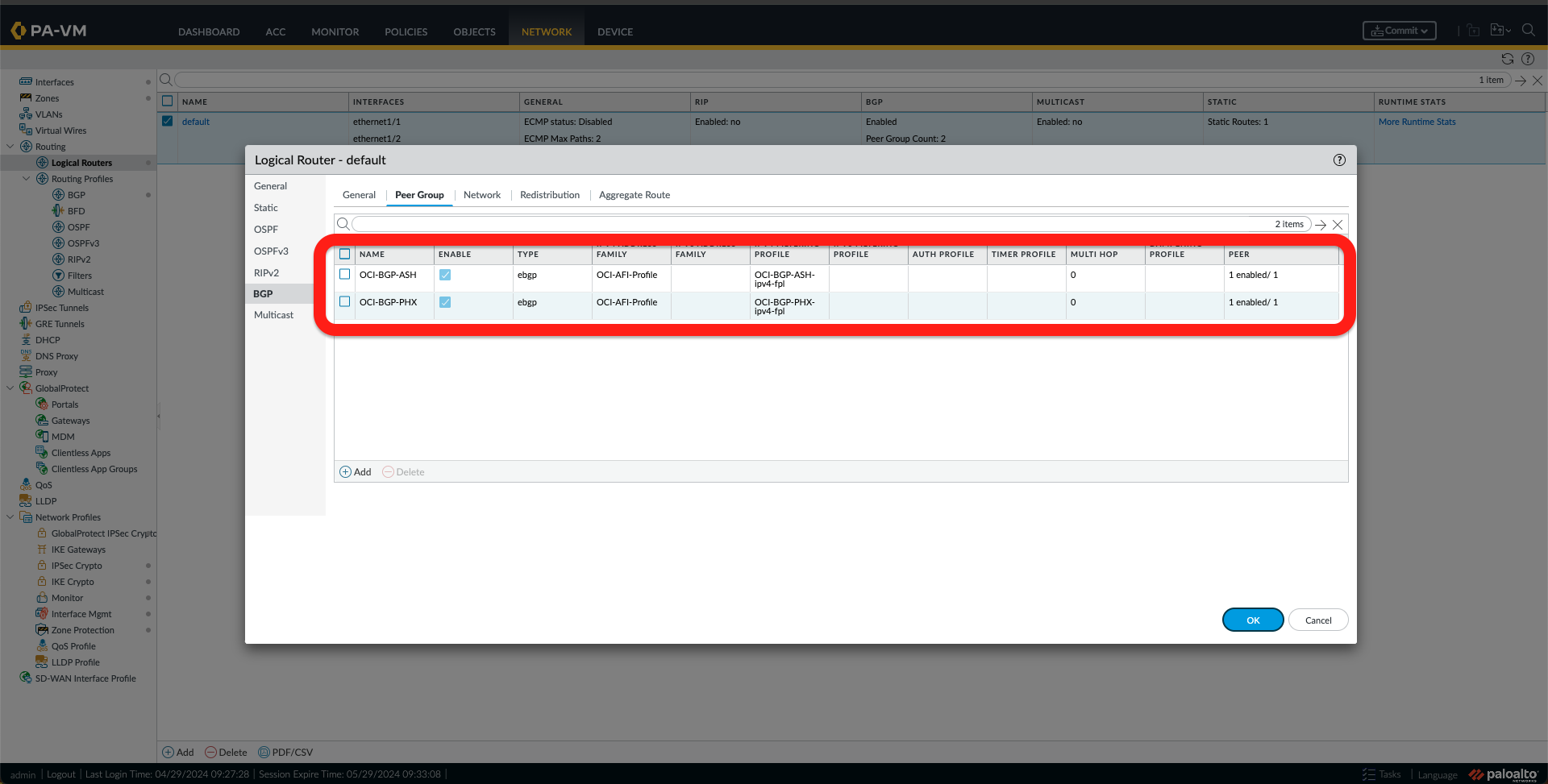
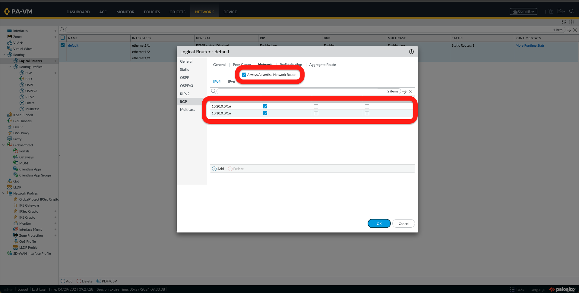
- Next, go to the Network tab and check that you have it as in the image below.
At this point, the Equinix Network Edge Virtual Device configuration using the Palo Alto VM-Series is complete.
Validation
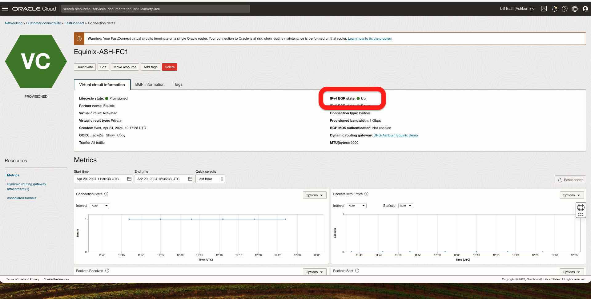
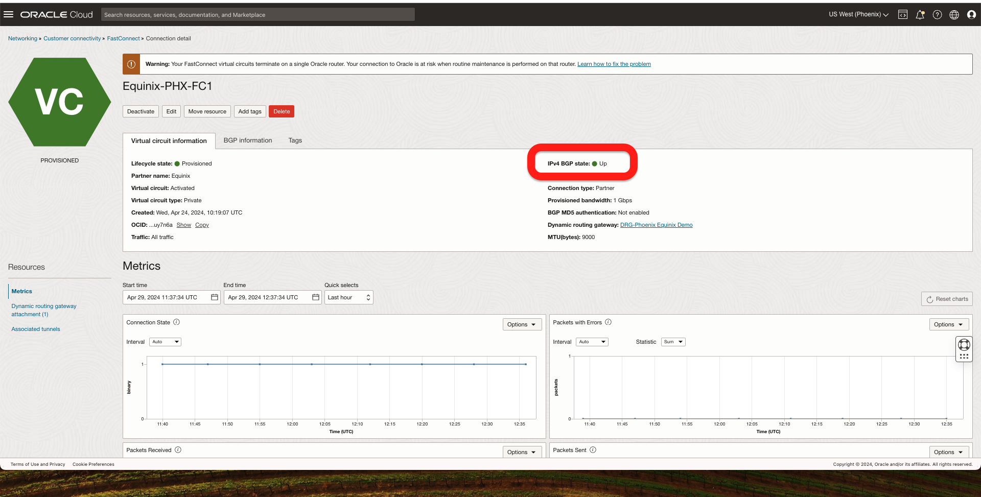
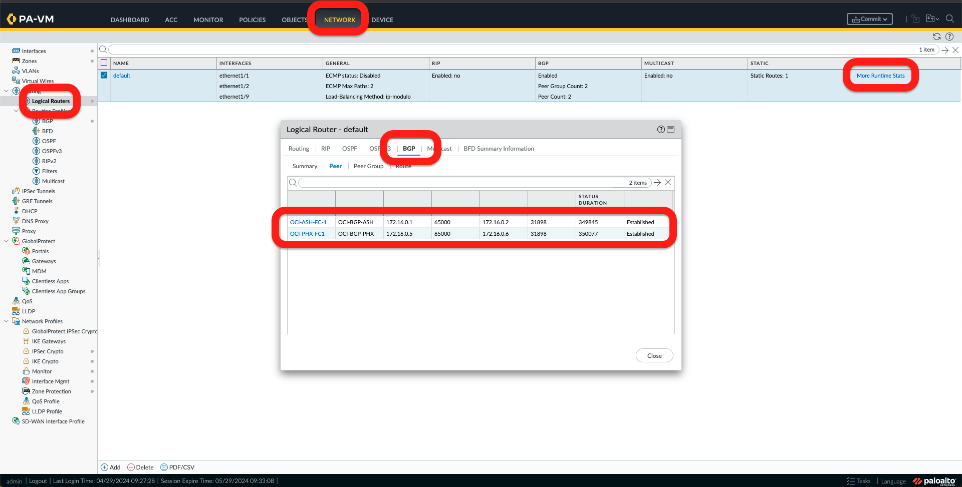
1. First, I should check the BGP connection to ensure it is UP. I can do it from 2 locations:
- From OCI console under FastConnect
- From the Palo Alto Network Edge Virtual Device, go to Network -> Logical Routers -> More Runtime Stats -> BGP, and I should see the BGP pees as established.
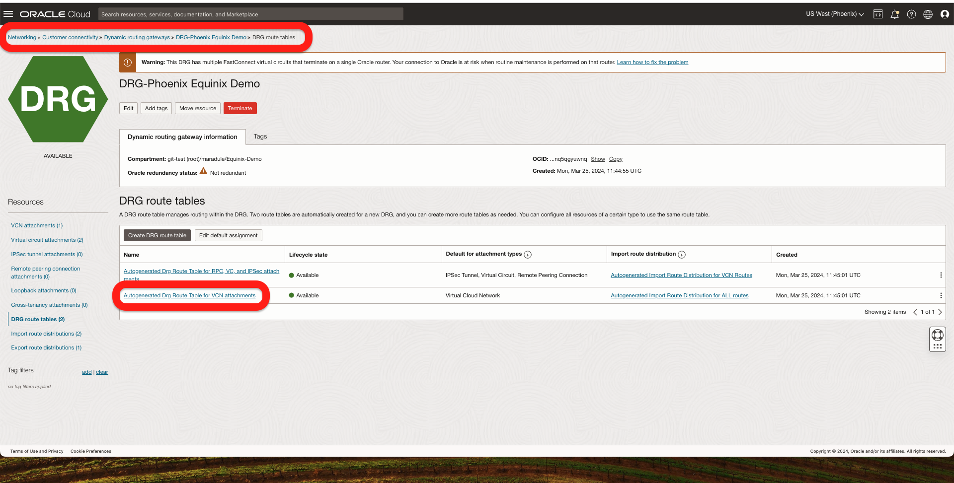
2. Received Routes in both ends:
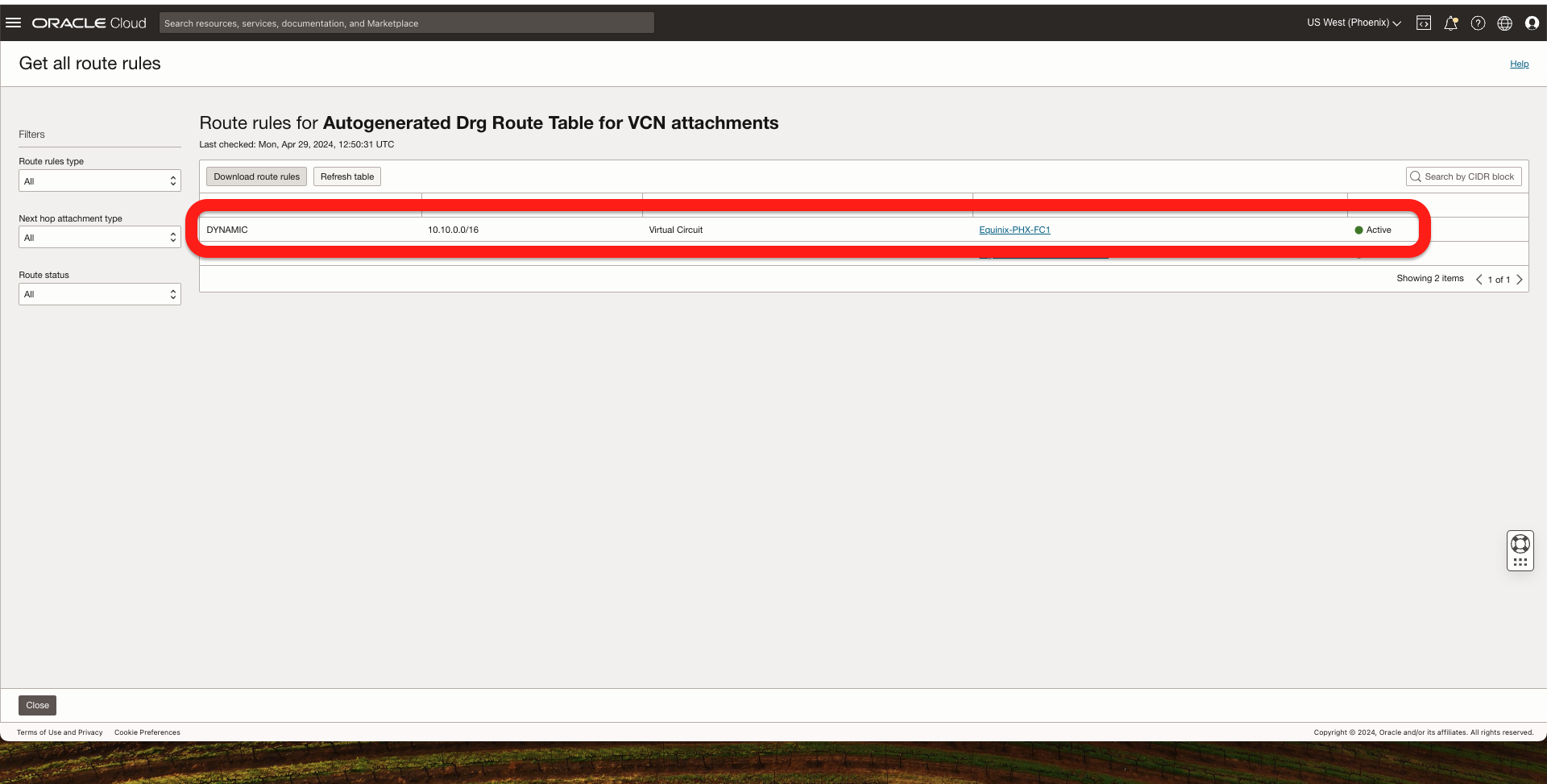
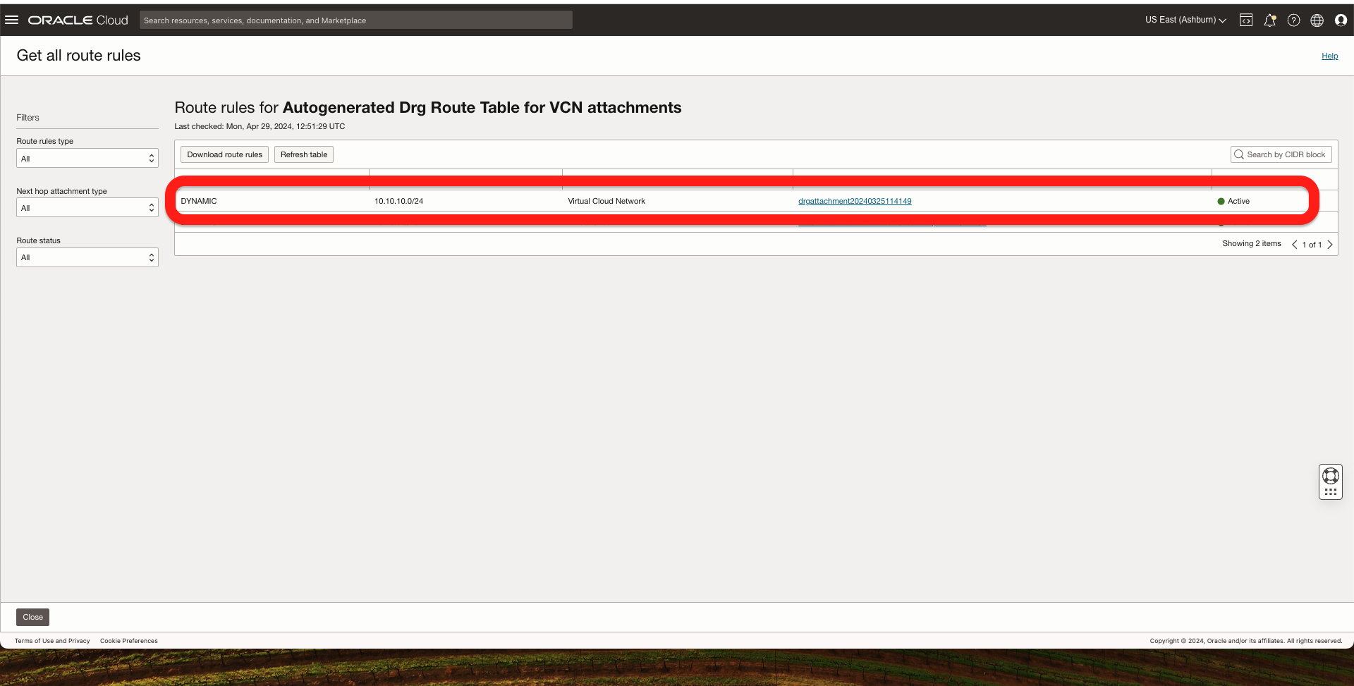
- On OCI, go to The DRG -> DRG Routing Tables -> Select the routing table that is attached to a VCN that should receive the routes from the FastConnect and click Get all routes:
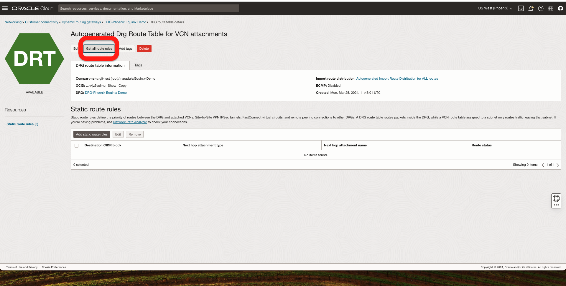
In the OCI Phoenix Region, I should see the Ashburn VCN CIDR coming from FastConnect.
In the OCI Ashburn Region, I should see the Phoenix VCN CIDR coming from FastConnect.
3. Now, I should have end-to-end connectivity between my two OCI Compute Instances.
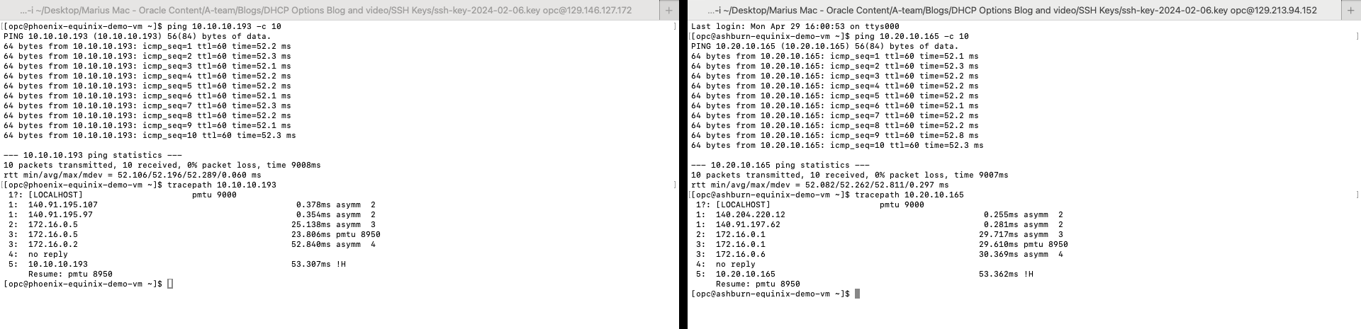
This concludes our test. I hope you enjoyed this blog. Thank you for reading!