The DRG L3 traffic separation was extensively debated if it can be handled or not. In the next blog post we will explore the L3 traffic separation by using specific DRG route tables when multiple VCNs with the same CIDRs are being attached to fulfil a specific traffic pattern requirement. In the next sections I will present a technical case required by some of my customers. The configuration was successfully implemented.
1. Network Topology
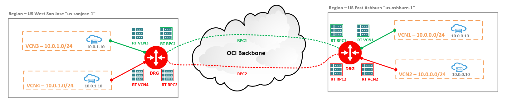
The networking diagram depicts two OCI regions, Ashburn and San Jose. Each region have two VCNs with the same CIDRs attached to the same DRG. For this example VCN1, VCN2 in Ashburn both with 10.0.0.0/24 as CIDR and VCN3, VCN4 in San Jose with 10.0.1.0/24 as CIDR have been defined. In each VCN there is a VM having 10.0.0.10 as an IP address in Ashburn and 10.0.1.10 in San Jose.
The IP path requirements are defined as follow: VCN3 <-> VCN1 (10.0.1.10 <-> 10.0.0.10) to follow the green path, VCN4 <-> VCN2 (10.0.1.10 <-> 10.0.0.10) to follow the red path. Between the two DRGs we have defined two RPCs, each with its own DRG RT attached. The same structure from the DRG RT perspective is used for the each of the VCN attachments.
The example can be expanded between OCI and On-premises, with the mention that we need to use multiple FastConnect VCs if FastConnect is used or multiple IPSec tunnels with different DRG RTs defined. On the CPE side, the VRFs needs to be used.
2. OCI Ashburn Configuration
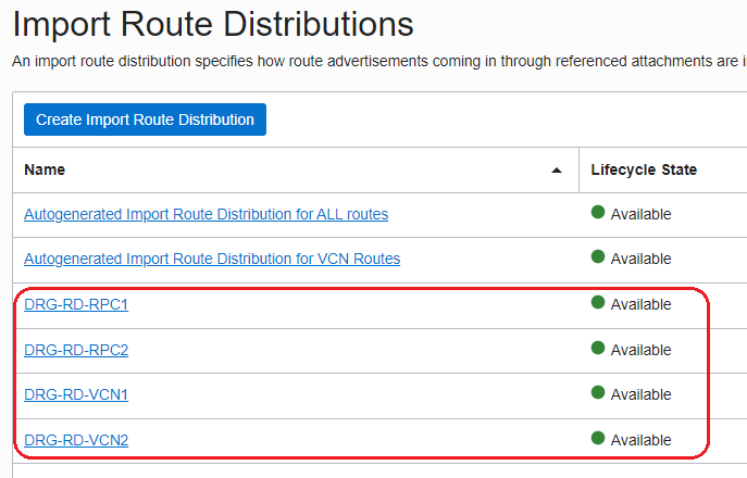
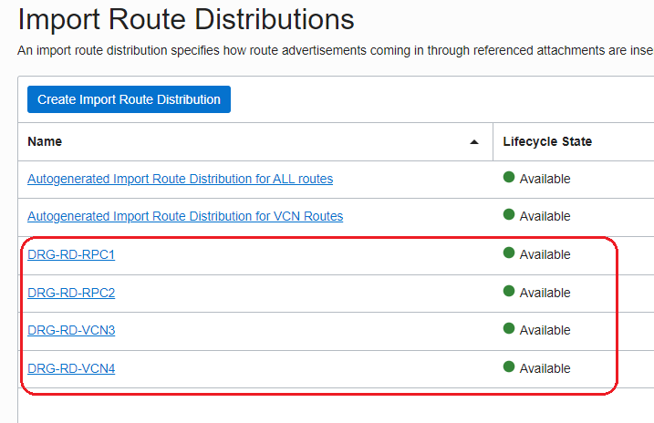
2.1 Create four new Import Route Distributions:
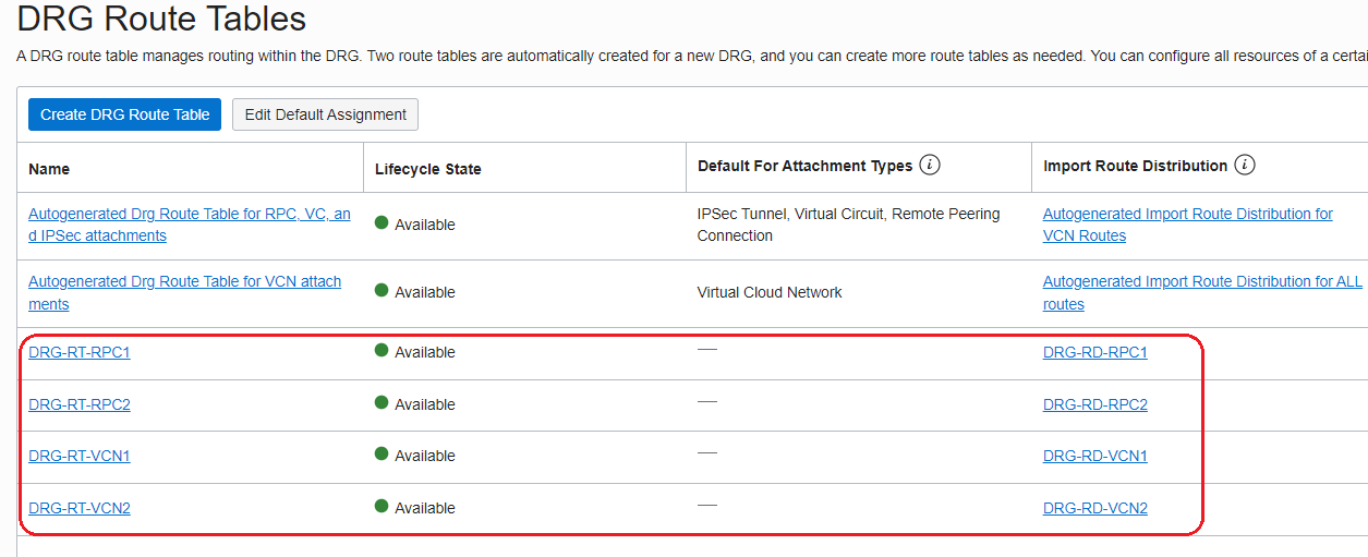
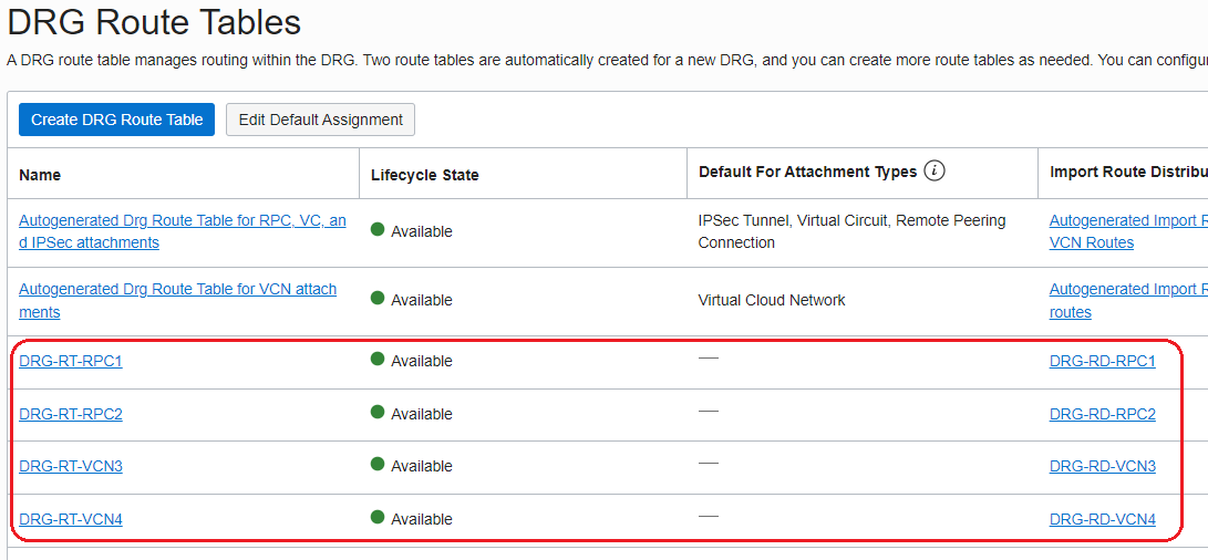
2.2 Create four new DRG Route Tables and associate the Route Distributions defined above as follows:
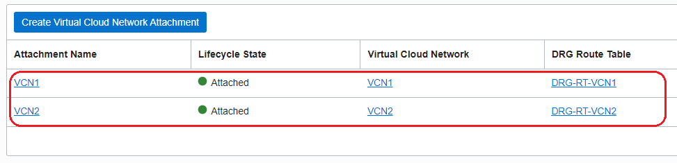
2.3 Attach the VCN1 and VCN2 to the DRG and configure the DRG route tables for the VCN attachments as follow:
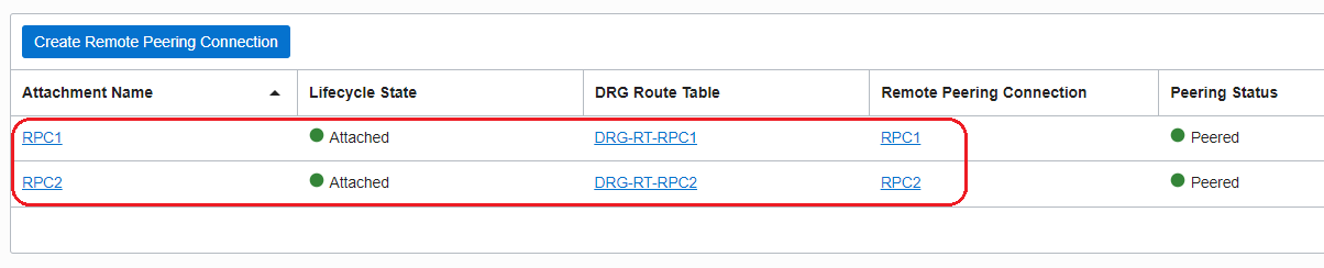
2.4 Create the two RPCs between Ashburn DRG and San Jose DRG and configure the DRG route tables for RPC attachments as follow:
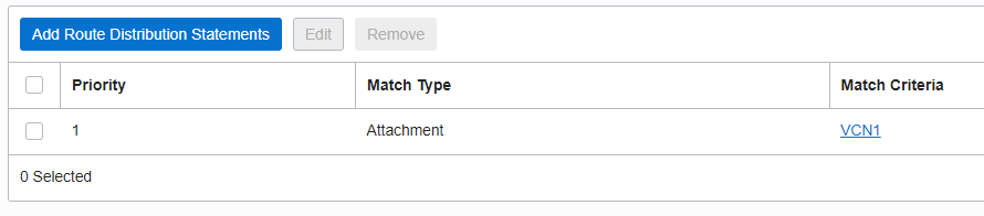
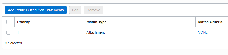
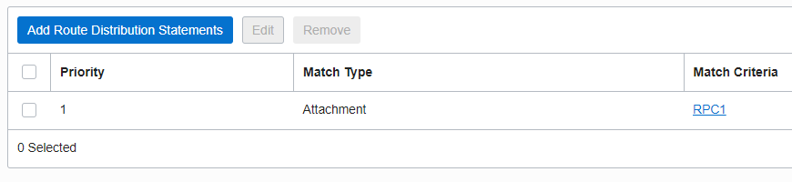
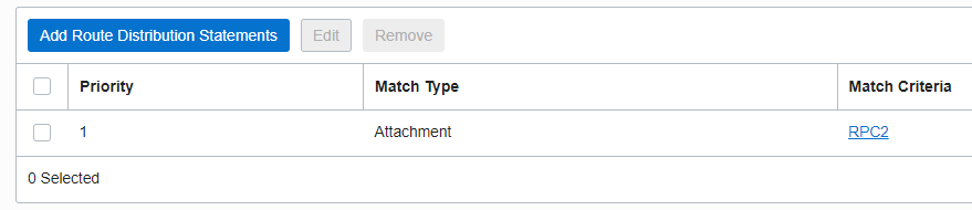
2.5 Configure the following import distribution rules:
DRG-RD-RPC1
DRG-RD-RPC2
DRG-RD-VCN1

DRG-RD-VCN2

2.6 Both VCN1 and VCN2 contains the 10.0.0.0/28 subnet;
3. OCI San Jose Configuration
3.1 Create four new Import Route Distributions:
3.2 Create four new DRG Route Tables and associate the Route Distributions defined above as follows:
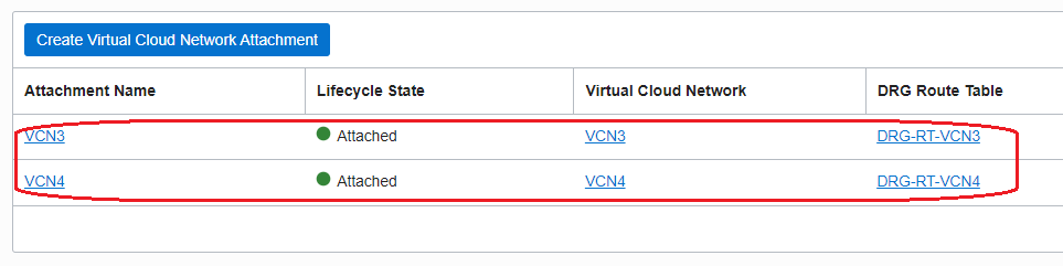
3.3 Attach the VCN3 and VCN4 to the DRG and configure the DRG route tables for the VCN attachments as follow:
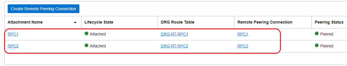
3.4 For the RPCs already in place, created at step 2.4, make sure the following DRG route tables for RPC attachments as used:
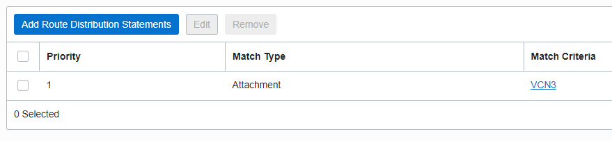
3.5 Configure the following import distribution rules:
DRG-RD-RPC1
DRG-RD-RPC2

DRG-RD-VCN3
DRG-RD-VCN4
3.6 Both VCN3 and VCN4 contains the 10.0.1.0/28 subnet;
4. IP Path Verification
From VCN3 to VCN1 using the green path:
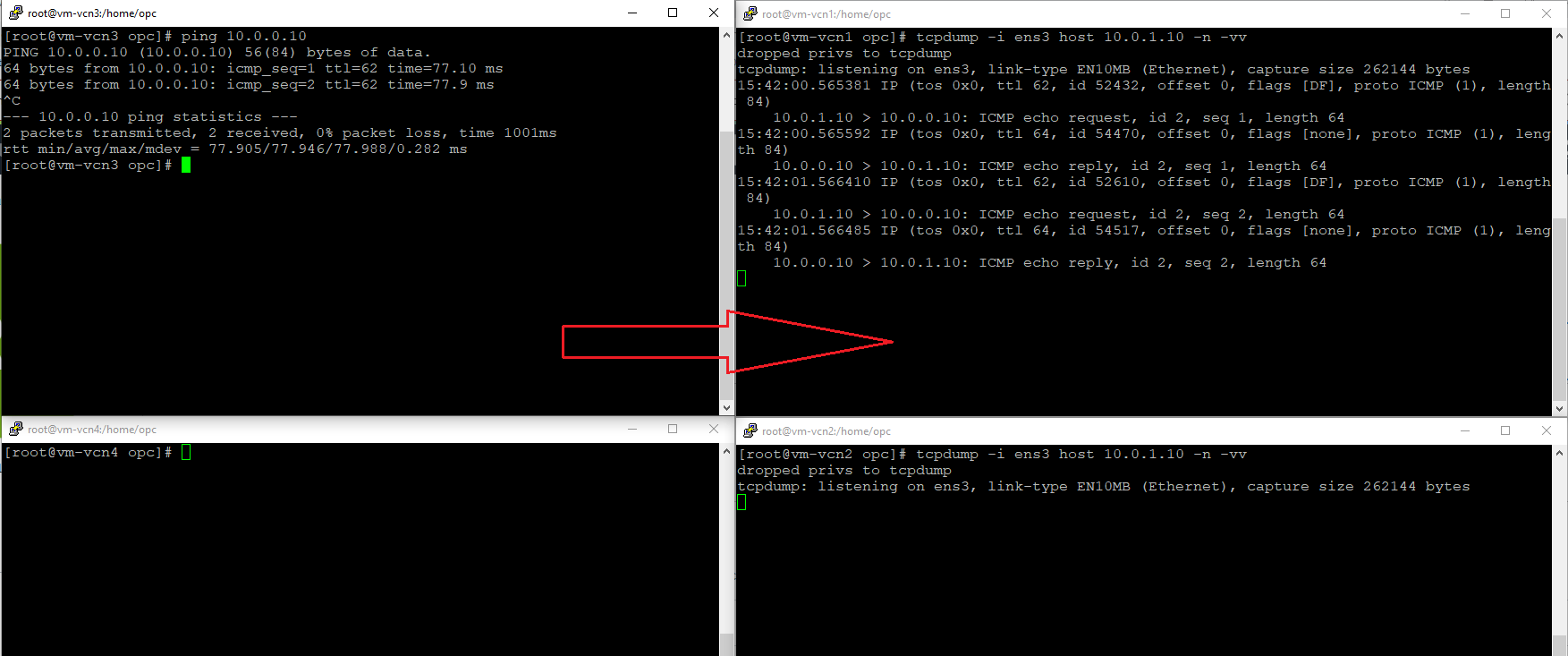
As we can observe, the green path defined between VCN3 and VCN1 is used, the tcpdump started on the VM from VCN1 confirms the traffic is received. Nothing received on the VM from VCN2.
From VCN4 to VCN2 using the red path:
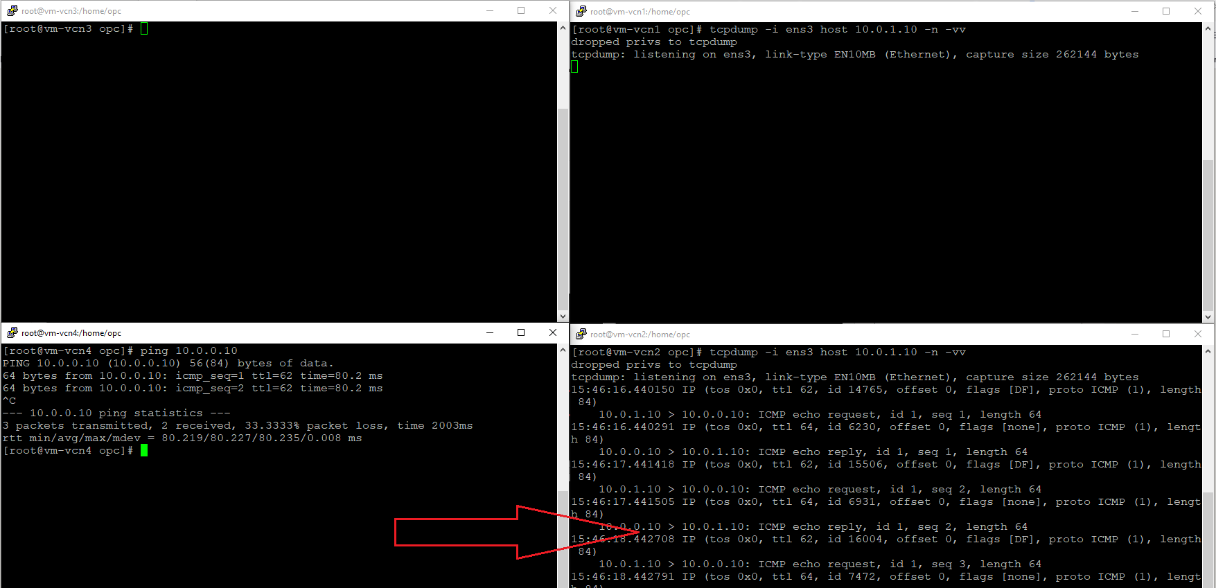
As confirmed by the tcpdump started on the VM from VCN2, the red path is used from VCN4 to VCN2.
As we can conclude, with the correct configuration in place the DRG can isolate the traffic when multiple VCNs with the same CIDR space are attached and route the traffic accordingly.