It’s been awhile since OCI announced the general availability of one of the most wanted Flexible Network Load Balancer feature, called Symmetric Hashing. Why this function is so important in our discussion?
Symmetric Hashing will allow the Flexible Network Load Balancer front-ends firewall appliances and handles both forward and reverse traffic. There is no need to perform any SNAT on the firewalls acting as FNLB backend serves. This simplifies the entire firewall configuration and provide end-to-end traffic visibility thanks to FNLB configuration that permits to act just as a “bump-in-the-wire”.
For more information related to Flexible Network Load Balancer and Symmetric Hashing: Enabling flexible security architectures with symmetric hashing on the OCI network load balancers and Symmetric Hashing.
The current state of our network includes a Security VCN where the Palo Alto Active/Passive cluster is configured. In this blog we will not discuss about Palo Alto Active/Standby cluster configuration. If you are interested in creating the Palo Alto Active/Standby cluster you can follow the blog post named Palo Alto VM-Series HA Deployment in OCI.
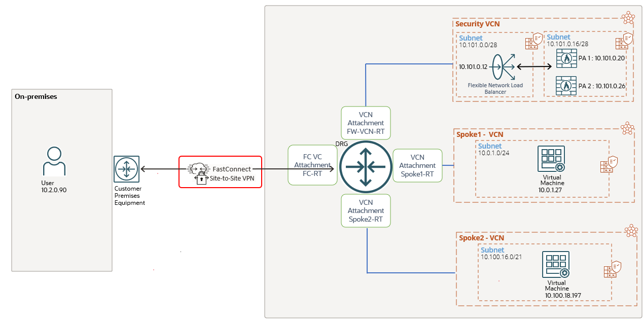
As you guessed, we are using the Hub and Spoke networking model with our Active/Passive cluster performing N-S and E-W traffic inspection. The following diagrams shows our current configuration:
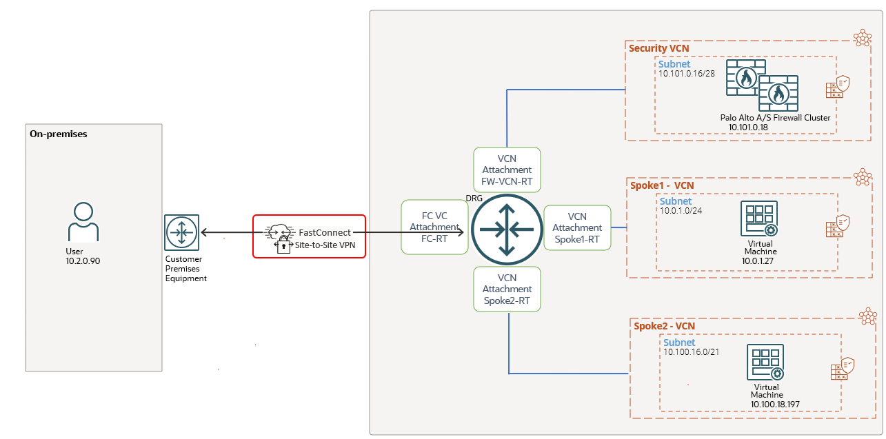
We are dealing with a Hub and Spoke type of architecture where the correct routing configuration will make the cluster to inspect and apply the security policies. In the following discussion we will analyze mostly the routing part of the design since our final goal if to include the OCI FNLB. We need to know how “hard” is from the routing change perspective to include the FNLB and to use both firewalls in Active/Active (once the cluster is disabled). This part if very important when we are dealing with a production network where the FNLB needs to be deployed.
Let’s look at the DRG routing configuration in place:
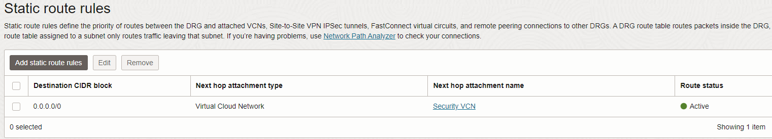
1. FC-RT DRG attachment route table:

The traffic from on-premises to the two IP prefixes listed above is directed to the Security VCN where our cluster lives. On another hand, the two static routes configured will trigger the two prefixes to be announced to the CPE by DRG using BGP.
The DRG will use its configured DRG VCN route table to enable the transit routing to the private IP address of the Palo Alto Active/Standby cluster.
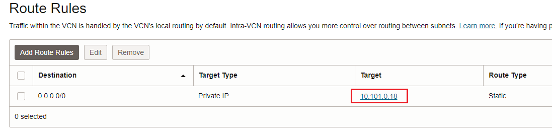
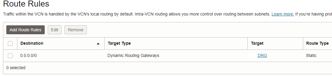
2. DRG VCN route table for transit routing:
3. FW-VCN-RT configuration:
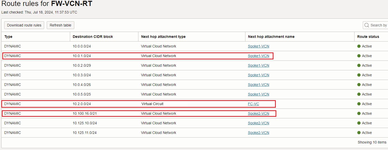
The DRG Security VCN attachment route table dinamically imports Spoke1, Spoke2 and on-premises routes received via the FC VC:
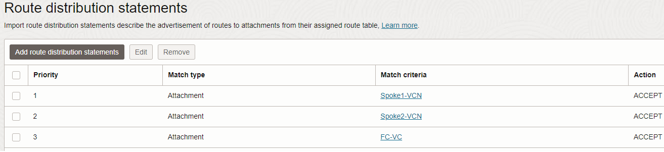
4. Each and every Spoke VCNs have their own DRG attachment route table, both containing the same route configuration:
Having analyzed the routing part, let’s get one step further and include the OCI Private Flexible Network Load Balancer with Symmetric Hashing. The new networking topology will look like:
The FNLB sits in its own subnet and both firewalls are configured as backend servers.
There are several points we need to explain and discuss here, as follows:
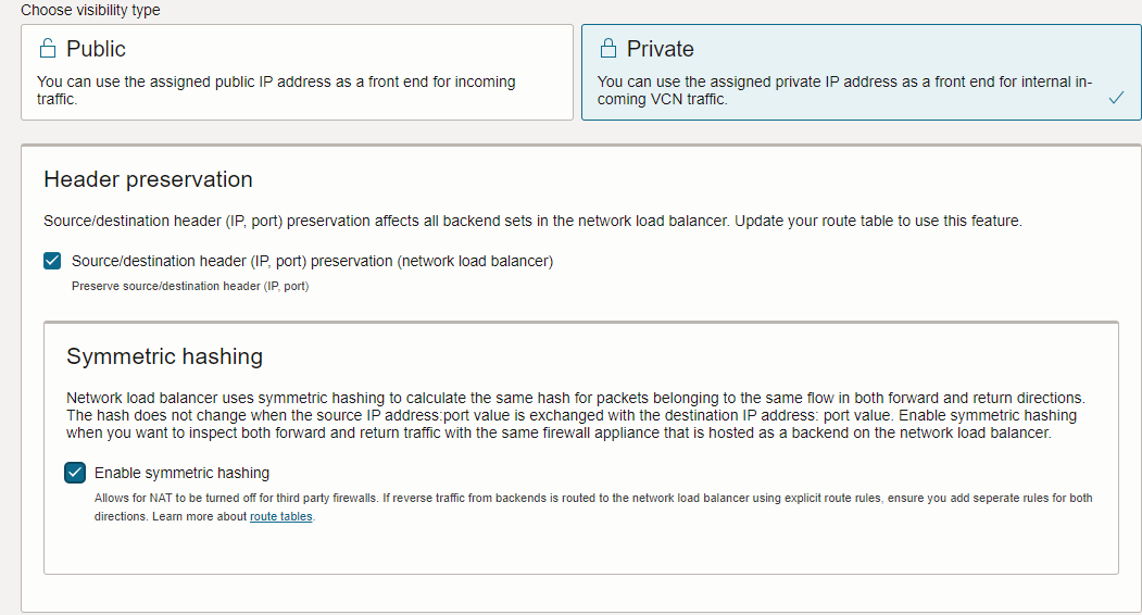
First point – During the FNLB creation, please make sure the Header preservation and Symmetric hashing options are both set:
Second point – We need to disable the Palo Alto Active/Standby cluster. After the cluster is disabled, we need to assign the primary IP address on each PA vnic that will be used for sending/receiving user traffic. If in your design you have multiple interfaces for sending/receiving the traffic (trust, untrust, etc.), you need to assign the primary IP address on each and every interface. In our example we are using a topology where the same PA interface is used for receiving and sending the traffic, a sort of “firewall on a stick” I would say.
Remember, the cluster is using only the secondary floating IP address and not the primary one.
To disable the cluster, start with your Standby node and under Device -> High Availability -> General -> Setup and uncheck Enable HA. Then, commit the configuration:
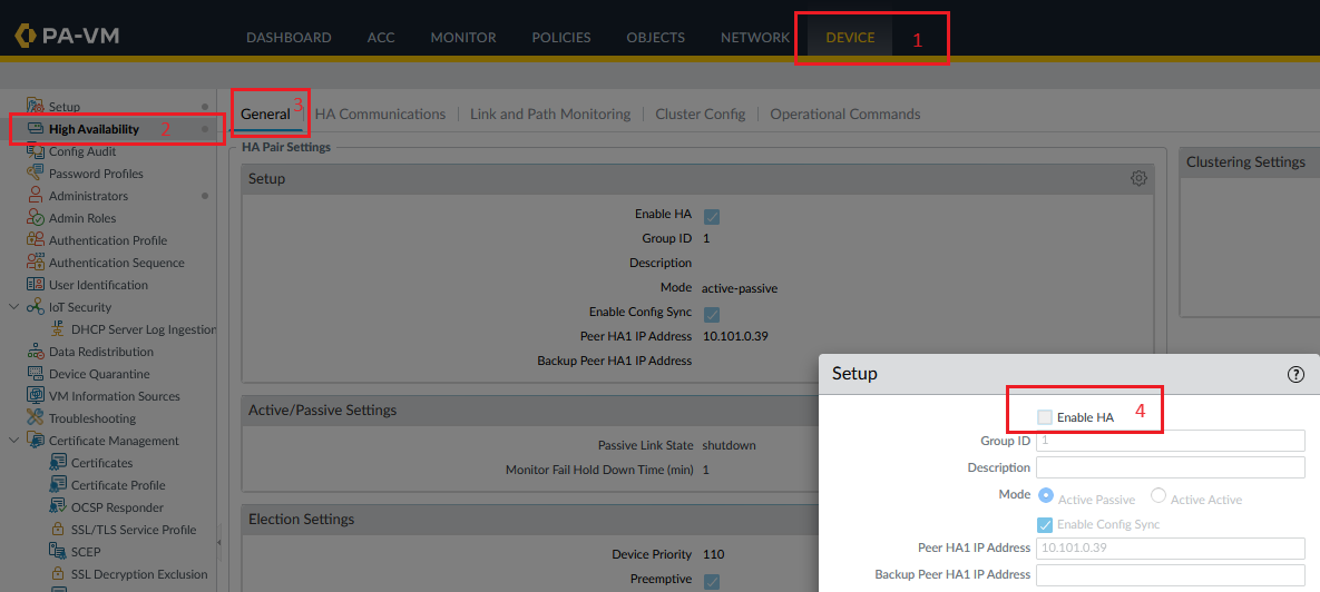
Perform the same operation on the Active node.
Once the second point is successfully completed, we should have two independent Palo Alto firewalls, ready to be configured as FNLB backend servers.
Third point – the route table attached to the firewalls subnet will not suffer any changes, will remain as is:
Fourth point – After both firewalls configured as FNLB backend servers are marked as healthy, we can proceed with the next steps:
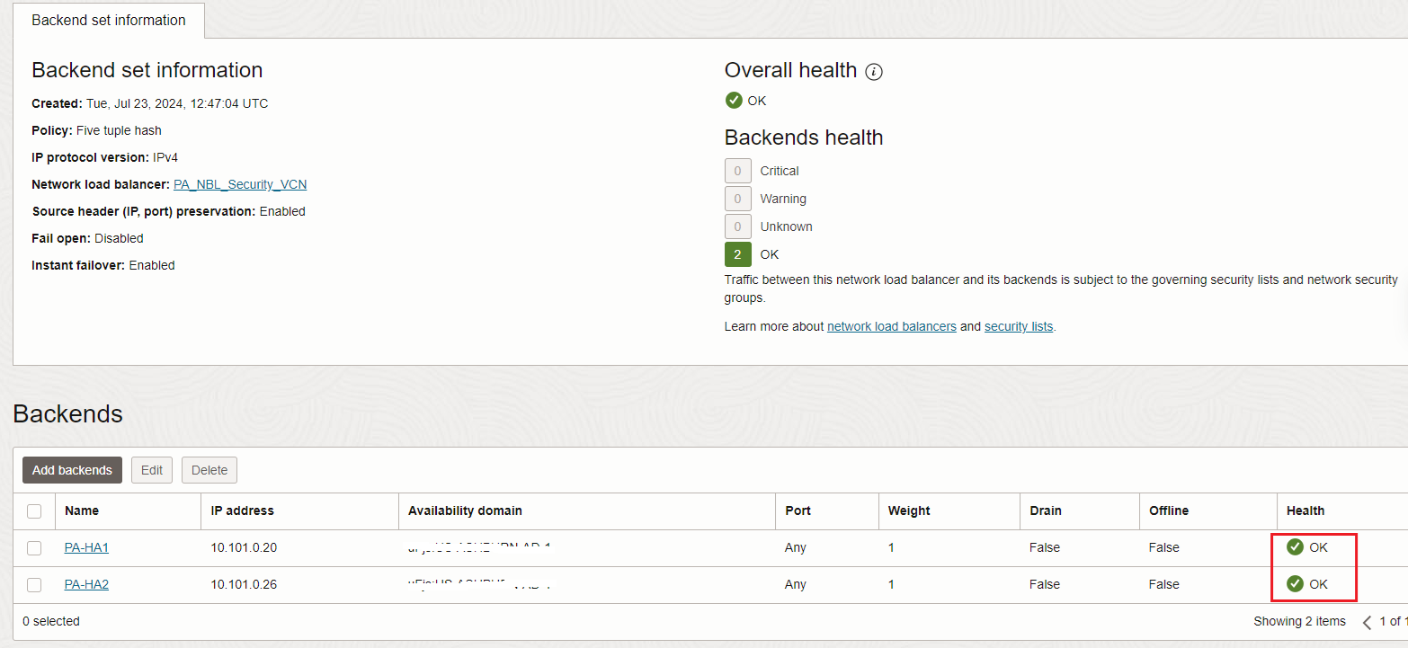
You need to make sure the health check and the user traffic is allowed between the FNLB and firewall subnet.
As you might notice, until now, we did not performed any changes in the routing configured at steps 1 to 4 above. Intentionally the step 2 was bolded, the single routing change will be performed in that route table. The change that will be performed is to direct the traffic from the cluster floating IP address (which was disabled) to the private IP address of the FNLB depicted in the new networking topology containing the FNLB, i.e. 10.101.0.12. Let’s change it:
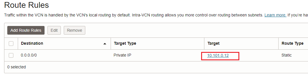
The conclusion so far is we need only to perform a very small change in the existing routing setup in order to accommodate the FNLB. Only one route entry was changed as we saw above.
Sure, we are not taking into consideration the FNLB deployment and disabling the cluster, which are separate activities.
Let’s verify if the user traffic is working just fine.
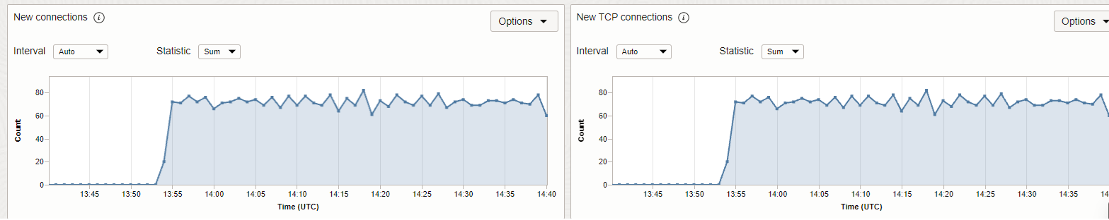
The very first traffic test will be between Spoke1 and Spoke2 using TCP:
And the TCP connections started to increase on the FNLB:
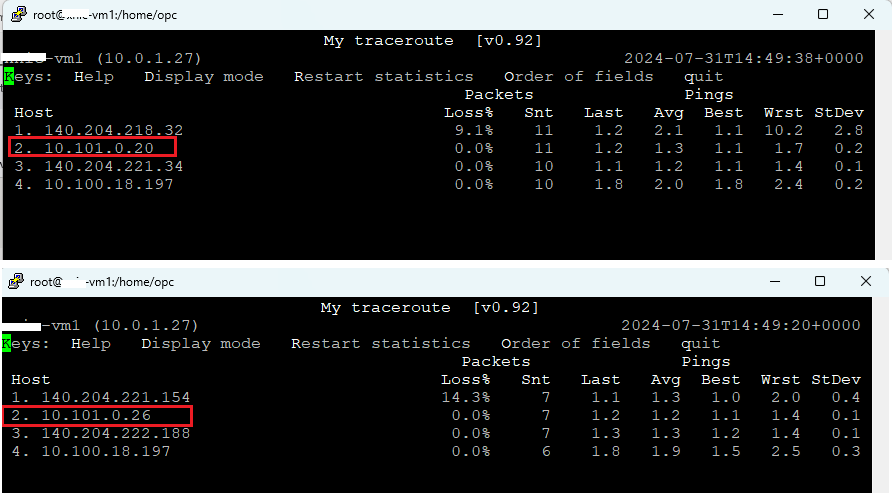
Running MTR from Spoke1 to Spoke2 or vice-versa will show the IP addresses of our firewalls:
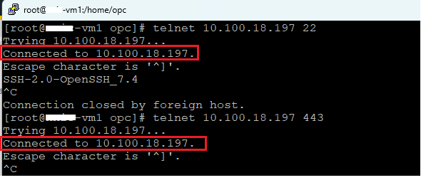
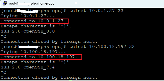
The second traffic test will be performed from on-premises to Spoke1 and Spoke2:
The MTR confirmed the right path is used:
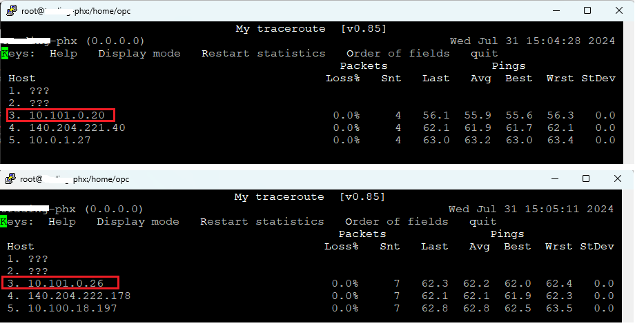
Now, our Palo Alto firewalls are running in Active/Active with the help of OCI FNLB and Symmetric Hashing function.