Oracle Cloud recently launched a service, Organization Management, which helps clients manage multiple OCI tenancies (accounts) in a centralized way. While that service is focused on the billing side, it opens discussions related to infrastructure architectures and how we interconnect multiple tenancies in OCI. The service model has a tenancy designed as a “parent” and all the other tenancies in the organization become “child” tenancies.
Cross-tenancy connectivity has been discussed before in multiple blogs on this site, some of which I will refer to because they contain detailed instructions on how to set it up. The purpose of this blog is to present some high-level architectures for clients that have multiple tenancies and want to:
– Have unified connectivity to destinations outside of OCI, either via private connections (FastConnect or IPSEC) or via the Internet.
– Control network flows between different tenancies in OCI, in a central place as opposed to allowing all tenancies to do mesh connectivity with each other.
There are 3 ways you can connect different tenancies in OCI:
1) Local Peering Gateways can peer two VCNs that belong to different tenancies
2) We can create DRG VCN Attachments cross-tenancy, where the DRG is in Tenancy 1 and the VCN is in Tenancy 2
3) We can peer 2 DRGs that sit in different tenancies with a Remote Peering Connection
We will explore each option, study the pros and cons and show a few diagrams. For each option, we will look into adding a network firewall to the mix. Sticking to the service model we will consider the parent tenancy as the hub of all connectivity while the child tenancies are simple application-focused deployments. Also, there are IAM policies specific to each architecture that need to be setup for the connectivity to happen.
Local Peering Gateways
LPGs are a low-latency option for peering 2 VCNs. A very simple diagram would look like this:
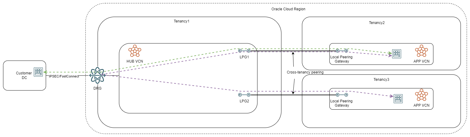
In this model, tenancy 1 (who could be the parent tenancy) acts as a hub of connectivity for all other tenancies, providing unified connectivity to the data center and child tenancy to child tenancy flows.
For the diagram above, the security controls can only be enforced at the endpoints, either inside each child tenancy or at the data center entry point, as the hub will only deal with routing. If we want to add a security layer in the hub we need to deploy a network firewall, in which case the diagram turns to:
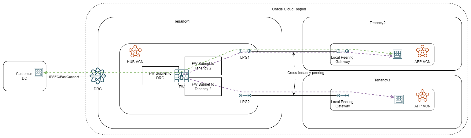
Note: the number of firewall interfaces is flexible, you can have an interface dedicated to each LPG/SPOKE or an interface dedicated for all spokes belonging to the same child tenancy or even a single interface for all spokes from all tenancies. The decision on that is based on many factors but the most important one is the shape and number of OCPUs assigned to the firewall as that limits the number of possible interfaces.
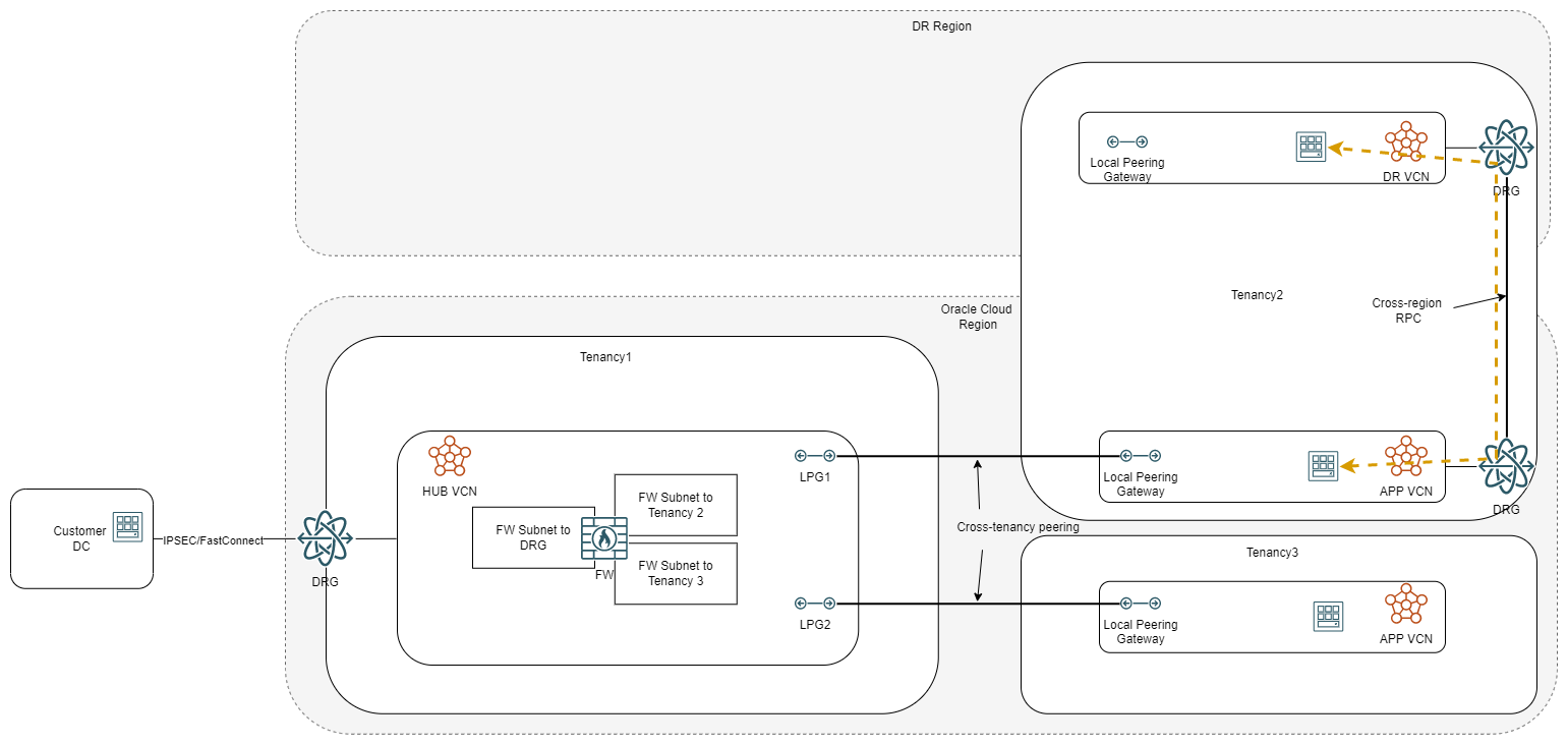
Disaster Recovery region
Most workflows in the cloud have some sort of a DR strategy that relies on connectivity to another region. In this case, the connectivity can be done in two ways, managed entirely by the child tenancy or through the parent tenancy. If the child tenancy manages its own DR connection, it would look like this:
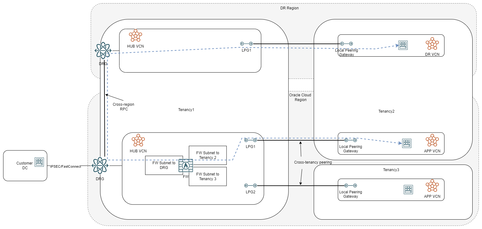
However, the DR connection can go through the parent hub too, like this:
Now let’s look at some PROs for using the LPG model:
a) It gives each tenancy a clear separation of roles; for example, the child tenancy can manage their entire infrastructure and only route to the parent tenancy to reach the data center; furthermore only parent tenancy network admins require IAM policies inside the child tenancy but not the reverse.
b) As the routing to LPGs is always static, no configuration in the child tenancy can affect the other tenancies. We will see in the other models that, if we leave everything dynamic, a child could affect the other tenancies by pushing a bad route.
c) Out of all the architectures, this is the only one that allows multiple firewall interfaces, dedicated to specific purposes (one interface per spoke, one interface per child tenancy, etc.). In the other cases, the firewall can only have a single interface.
d) Considering that a VCN can only be peered to one DRG, using the LPG to go to the parent tenancy gives a lot of options to the child tenancy as they can use their own DRG for other connectivity such us their own hub-and-spoke model or a DR region.
Let’s also look at some CONs:
a) As each spoke requires its own LPG in the hub, the architecture has some limitations regarding scaling; in a scenario with 3-4 child tenancies, each with 5 VCNs or more, the hub would have 15-20 LPGs which would make operations (routing rules, troubleshooting) a pain.
b) While this point was on the “pro” side it can also be on the “con” side – no automatic routing updates. Adding subnets/CIDRs in the spokes requires manual routing updates in the hub.
If you want to implement this in your tenancies you can use our official documentation or this great blog post.
Cross-tenancy DRG VCN Attachments
The second method for cross-tenancy networking revolves around connecting VCNs from one tenancy to a DRG which sits in a different tenancy. A very simple architecture would look like this:
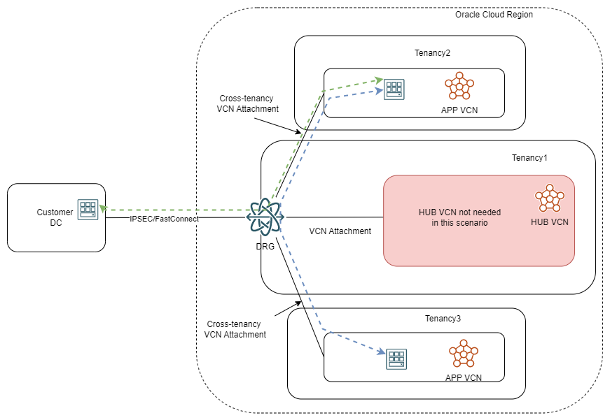
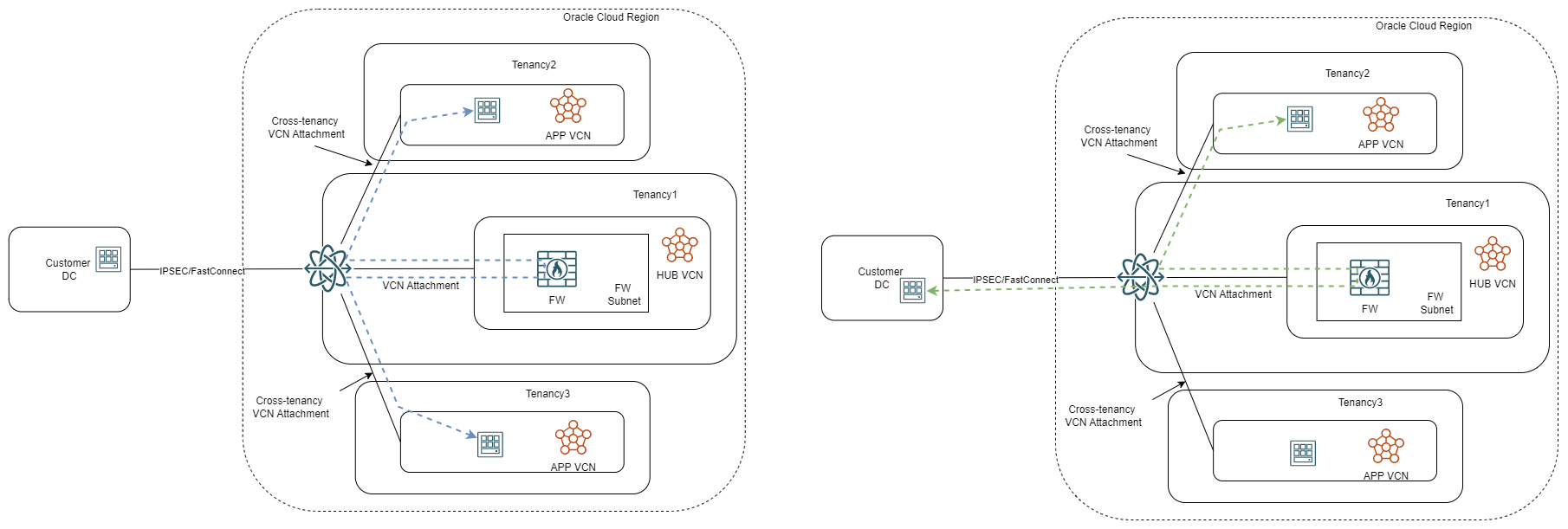
When not using a firewall, the DRG in the parent tenancy becomes the hub of all connectivity and will control OCI to on-premises or tenancy to tenancy flows. Adding a firewall to the mix would look like this:
In this model, the connectivity to a different region would be controlled by the parent tenancy with cross-region Remote Peering Connections in the DRG.
PROs:
– The DRG can support up to 300 attachments so you have a lot of room to grow;
– It can be viewed both as a PRO and a CON, the parent tenancy network admins have a lot more control over the network flows of the child tenancies; also, the child tenancy admins cannot add new VCNs, they will have to involve the parent tenancy admins.
– Routing updates are automatic, a new CIDR added to an existing VCN will be automatically advertised to everything else connected in that DRG.
CONs:
– The IAM policies are a little more complicated than in the LPG model. Furthermore, in order for the child tenancy admins to be able to see or use route tables that reference the DRG, their group will need policies in the parent tenancy.
– Contrary to the LPG model, the firewall will have one interface for all traffic (router on a stick).
– The child tenancies become fully dependent on the parent tenancy for any connectivity, even VCN to VCN inside their own tenancy (unless they deploy LPGs for that). Connecting new VCNs in the child tenancy to the DRG is managed by the admins of the parent tenancy.
If you want to implement this in your tenancies you can use our official documentation or this great blog post.
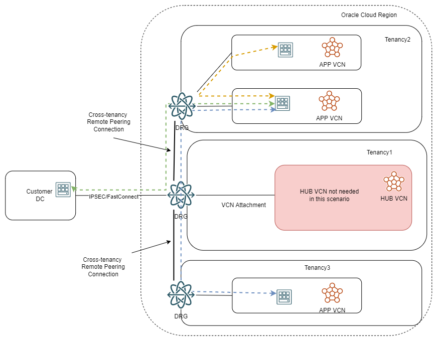
Cross-tenancy DRG Remote Peering Connection
The last method for cross-tenancy connections is to leverage the Remote Peering Connection construct in the Dynamic Routing Gateway. In this model, each tenancy has its own DRG and we peer the DRGs between tenancies. A high-level diagram would look like this:
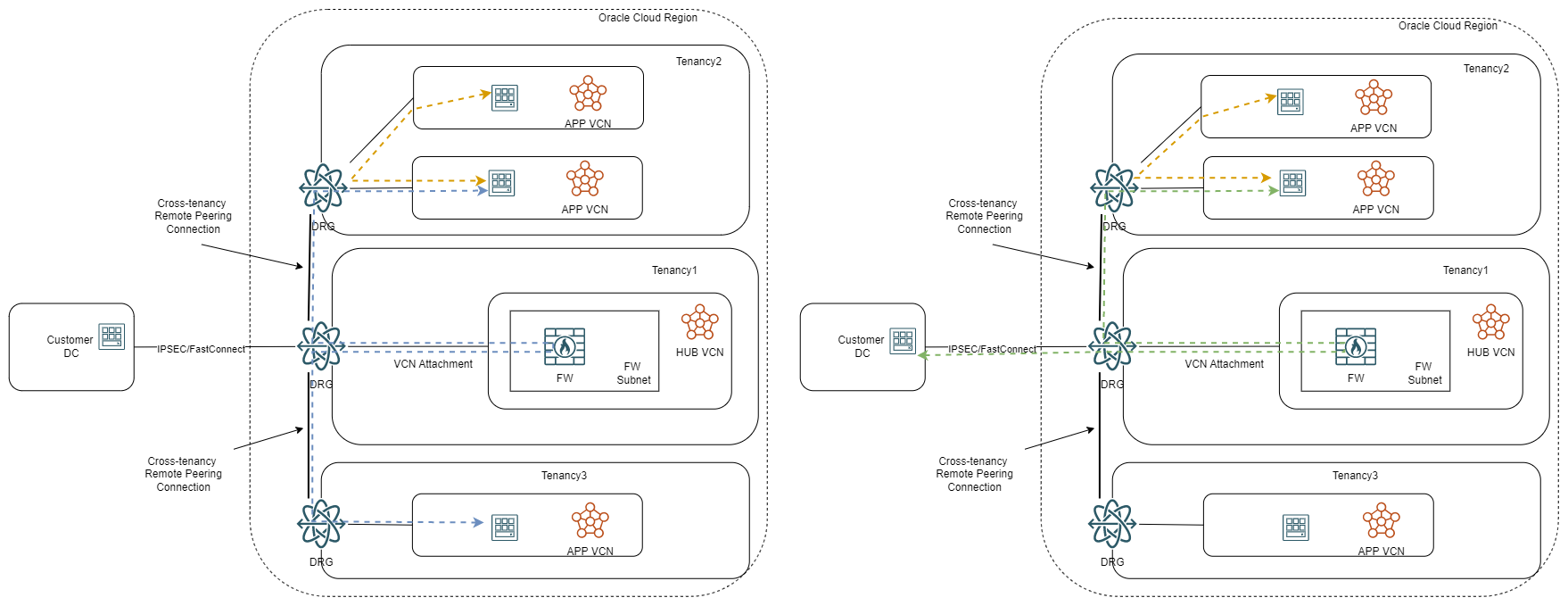
If we want to add a firewall in the parent tenancy, it would look like this:
PROs:
a) The main attraction of this architecture is that each tenancy is independently managing its network. They can scale up or down and add workloads, subnets or VCNs without involving the parent tenancy admins.
b) The parent tenancy admins will have to manage a single RPC to each child tenancy which greatly simplifies routing and troubleshooting.
c) Routing can be both dynamic or, should the tenancy admins want it, switched to static.
d) The RPC can be done in the same region or across regions; this is the only architecture that allows the parent tenancy to be in a different region than the child tenancy.
e) He IAM policies are similar to the LPG model and don’t involve giving any access in the parent tenancy to the child tenancy admins.
CONs:
a) If left with automatic routing updates, a mistake in a child tenancy (adding the wrong route or CIDR in a VCN) can impact other tenancies.
b) The firewall will have a single interface for all traffic similar to the VCN attachment architecture.
c) RPC to RPC or RPC to FastConnect communication requires extra work to set up.
If you want to implement this in your tenancies you can use our official documentation or this great blog post.
Final note
OCI’s networking constructs provide a lot of flexibility for cross-tenancy architectures. Referring to the three methods presented above, each one has its own use case so there is no right and wrong.
