Introduction:
Welcome to the 1st part of the Palo Alto Hub and Spoke deployment on OCI blog-series.
You can read main page and 2nd part of the series here:
Palo Alto Hub and Spoke deployment on OCI – Main Page
Palo Alto Hub and Spoke deployment on OCI – Part 2
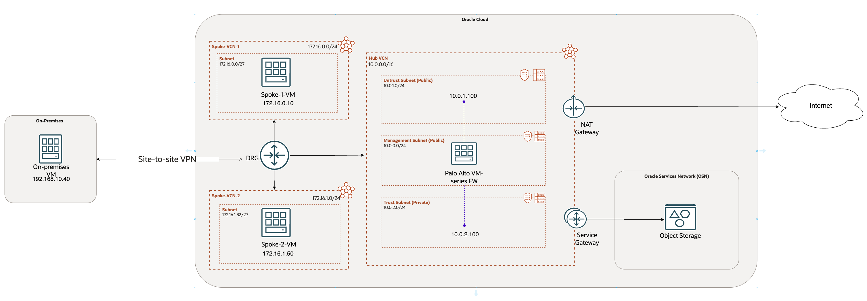
In this blog, we will cover the scenario where we extend the Palo Alto interfaces locally in the Hub VCN.
This approach is appropriate when you:
- Want to assign all the spoke VCNs to a single zone
- Reduce the total number of interfaces
- Keep the management of the PA VM in the same local VCN for simplicity
Pre-requisite:
Before reading this blog, please visit the main page of this blog-series as a pre-requisite:
Palo Alto Hub and Spoke deployment on OCI – Main Page
Main page covers the scope, and all the baseline configuration required for this blog.
Network Diagram:
In this blog, we will explore the 1st scenario mentioned in the main page.
We have basic configuration ready in the previous section. Now let’s continue with rest of the configuration.
OCI configuration:
- Spoke VCNs:
For this use case, I have provisioned 2 spoke VCNs with 2 private subnets in it. 2 VMs, Spoke-1-VM and Spoke-2-VM are provisioned in their respective VCNs.
- VCN Peering:
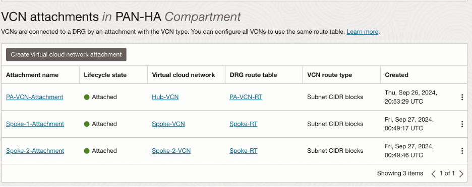
Since we are extending the interfaces in the local Hub VCN only, we will need to peer spoke VCNs and Hub VCN together with the help of DRG. We will have 3 VCN attachments at the DRG as follows:
Please refer to this documentation for VCN peering:
https://docs.oracle.com/en-us/iaas/Content/Network/Tasks/scenario_d.htm#scenariod
We will have a look at the routing shortly.
- OCI Routing:
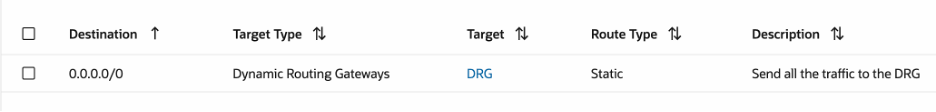
- Spoke VCNs routing:
We want to inspect all the traffic coming in and out of spoke VCNs. Hence, we will send all the traffic to the DRG:
- Hub VCN routing:
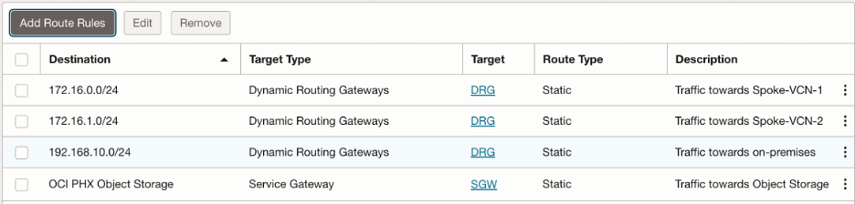
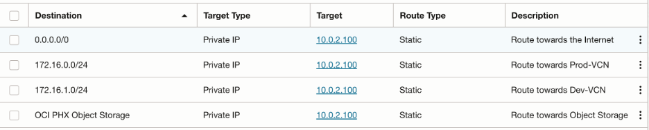
- Trust subnet route table:
We want to send following traffic to the DRG:
- Towards Spoke-VCN-1
- Towards Spoke-VCN-2
- Towards on-premises
Also, we will use Service Gateway to send all the traffic towards Object Storage. In summary, trust subnet route table looks like this:
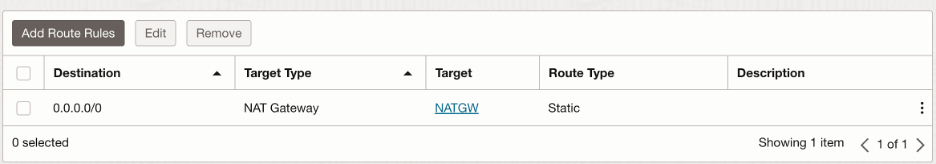
- Untrust subnet route table:
We want to send all the outbound traffic to the public internet via NAT Gateway:
- DRG routing:
- Hub VCN attachment transit route table configuration:
In Hub VCN, we need to create a new transit route table, which we will associate with Hub VCN attachment at the DRG (also known as transit routing via private IP). We want following traffic to be inspected through the trust interface:
- All the internal traffic destined towards Spoke VCNs/On-Premises
- All the traffic going out to the internet from the spoke VCNs
- All the traffic going to the Object Storage
Hence, this route table looks as follows:
NOTE: You can argue that 0.0.0.0/0 covers all the IP ranges, so why add individual CIDR blocks again? Most of the OCI customers use BGP for their VPN tunnel. FastConnect also supports only BGP. The routes added in this transit route table will be advertised over the BGP session to the on premises. We have added 0.0.0.0/0 to cover all the traffic to the internet. Most of the times, on premises network design do not allow gateways/routers to install the default route in their route table. In such cases, customers can simply accept rest of the IP ranges, without impacting the functionality.
At DRG, Hub VCN imports routes from both the spoke VCNs as well as VPN:

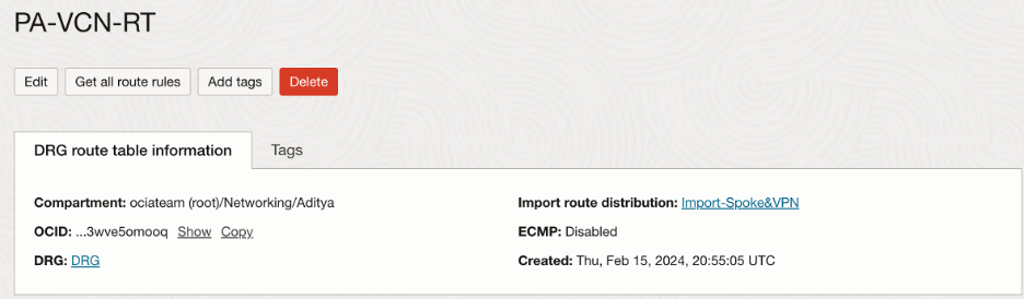
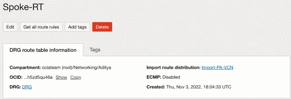
- Spoke VCNs attachment route table configuration:
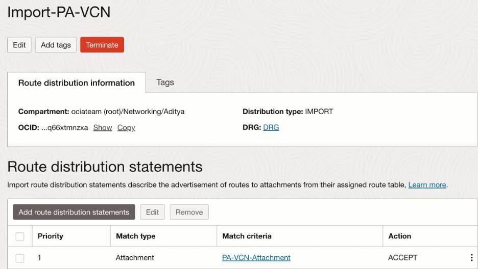
We will need Spoke VCNs to import routes only from the Hub VCN so that all the traffic originating will be forwarded to the Palo Alto firewall first. Hence, we will take advantage of customized import route distribution and route table as follows:
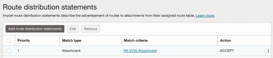
In the import route distribution, we import the Hub VCN attachment:
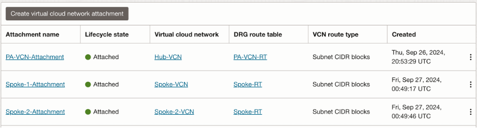
Summary of the VCN attachments:
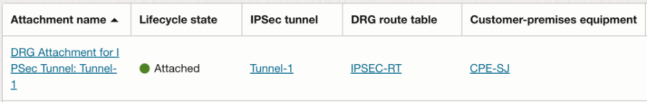
- VPN tunnel attachment route table configuration:
Like Spoke VCNs, we will need the VPN tunnel to import routes only from the Hub VCN so that all the traffic originating will be forwarded to the Palo Alto firewall first.
The import route distribution and route table for the VPN tunnel attachment looks as follows:
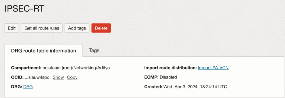
After creating the route table, we need to associate it with the VPN tunnel attachment which then looks as follows:
Palo Alto Configuration:
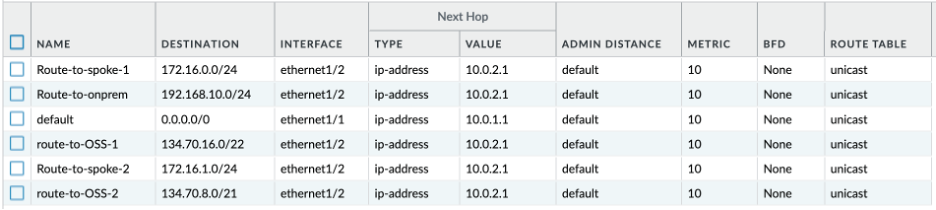
We need following rules in the Palo Alto router:
- Traffic destined towards spoke VCNs/on premises CIDR blocks, and Object storage IP ranges forwarded to the gateway IP of the trust subnet (In this case, 10.0.2.1)
NOTE: You can get all the OSN public IP ranges, including those for Object Storage in:
https://docs.oracle.com/en-us/iaas/tools/public_ip_ranges.json
- Traffic towards the public internet forwarded to the gateway IP of the untrust subnet (In this case, 10.0.1.1)
Verification:
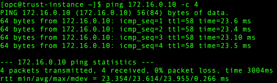
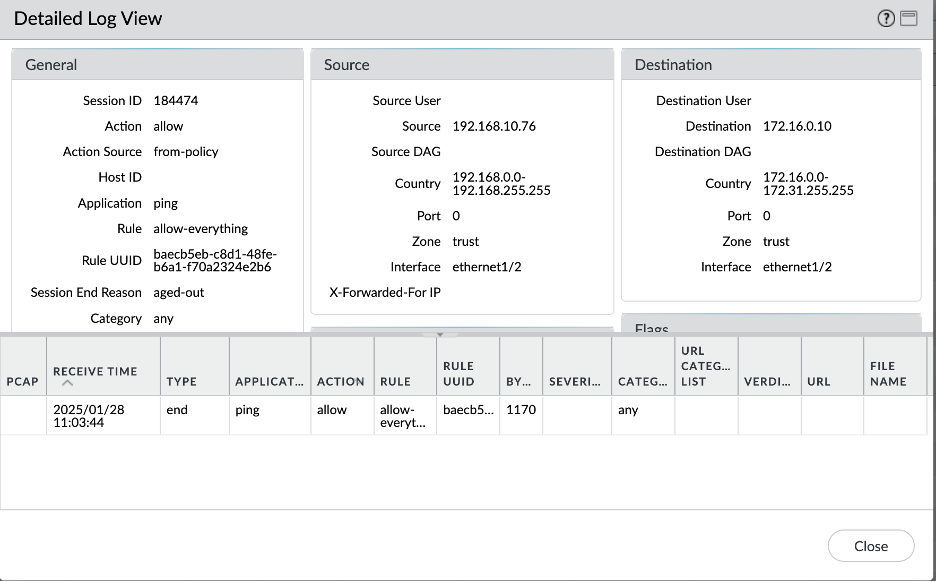
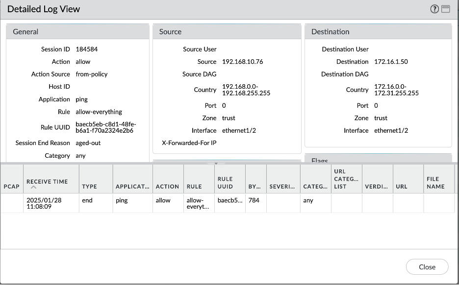
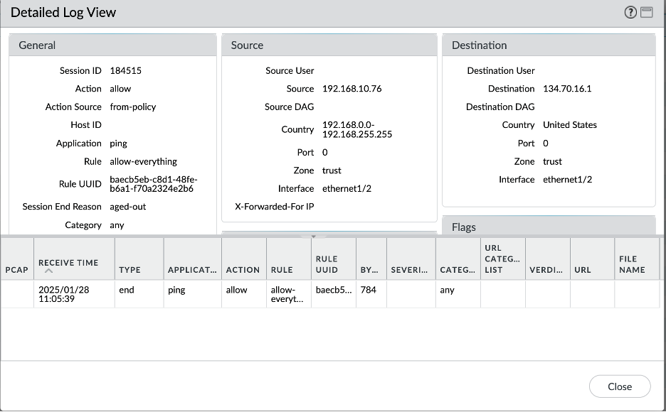
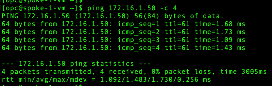
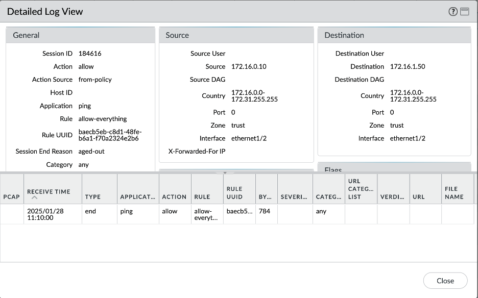
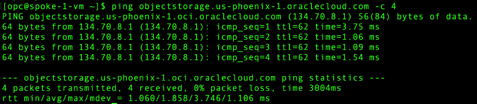
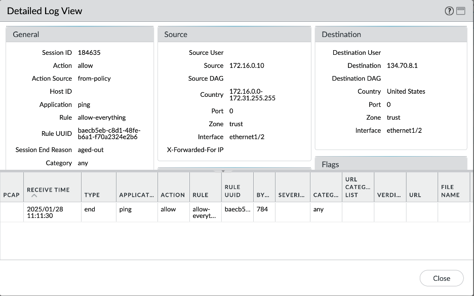
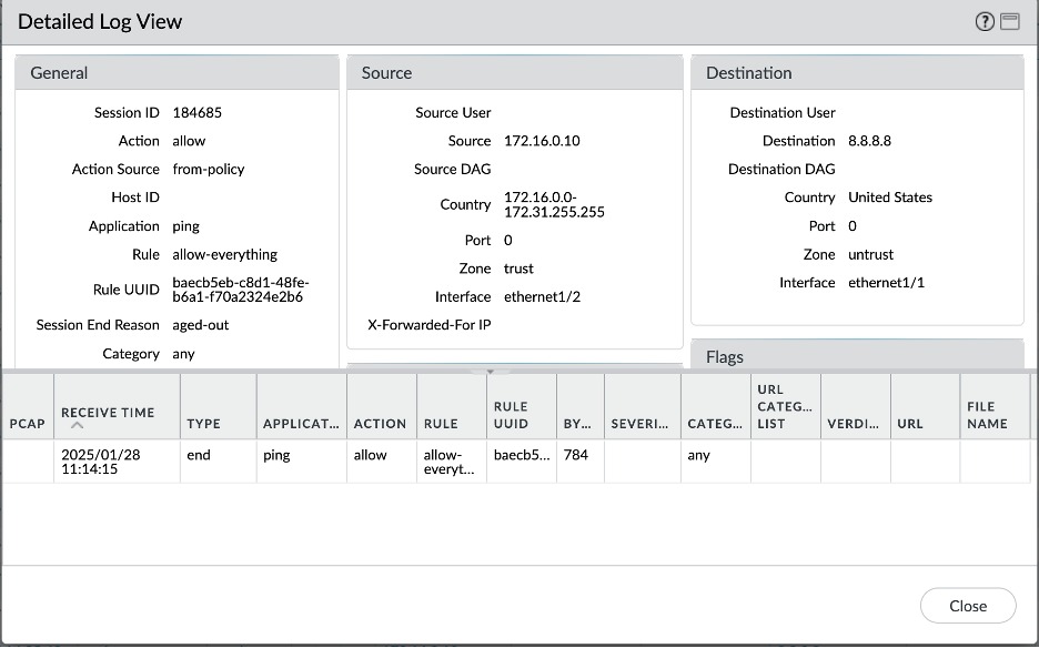
Let’s verify all the scenarios one by one. Connectivity screenshots are followed by the Palo Alto logs screenshots to verify that the intended traffic is being passed through the Palo Alto for inspection.
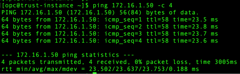
- On-Premises – Spoke VCN-1 connectivity:
- On-Premises – Spoke VCN-2 connectivity:
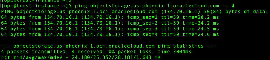
- On Premises – Object Storage connectivity:
- Spoke VCN 1 – Spoke VCN 2 connectivity:
- Spoke VCN 1 – Object Storage connectivity:
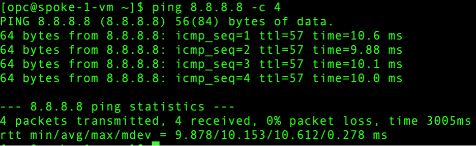
- Spoke VCN 1 – Internet connectivity:
Conclusion:
This concludes the first part of our blog-series where we explored first hub and spoke model scenario to extend VNICs in the local Hub VCN.
In the second part of this series, we will go over the 2nd scenario of implementing the Palo Alto Hub and Spoke model, where we extend VNICs individually into the Spoke VCNs