Introduction
In today’s cloud-driven world, ensuring seamless connectivity between on-premises and cloud is more crucial than ever.
One of the critical elements in achieving this is establishing a VPN connection.In this blog, I will walk you through the process of establishing a VPN connection from Firepower Threat Defense(FTD) to OCI.
Whether you’re looking to enhance your hybrid cloud setup or simply improve network security, this blog post will provide you with the essential knowledge and practical steps to get started.
Prerequisites
There are several requirements and prerequisites to be aware of before moving forward.
- Knowledge of basic OCI networking service components.
- Knowledge of Cisco FTD VPN.
- Creation of Cloud Network Components (VCN, Subnets, DRG, Internet Gateway).
Agenda
- OCI – Create CPE Object.
- OCI – Create IPSec Connection.
- Cisco – Create VPN Connection.
- Cisco – Configure Static Routing.
- Verification.
Create CPE Object
- Log in to the OCI dashboard.
- Navigate to the Networking section from the hamburger menu.
- From the Customer Connectivity list click on Customer-premises equipment.
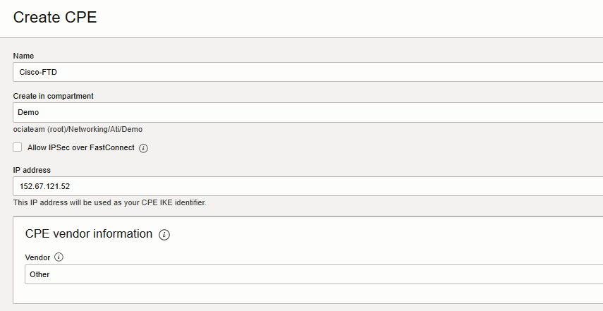
- Click “Create CPE”Enter the following values:
– Create in Compartment: select the compartment for the VCN you want.
– Name: A descriptive name for the CPE object.
– This example uses “Cisco-FTD” as the name.
– IP Address: Enter the public IP of your Cisco FTD outside Interface.
– CPE Vendor: Select Other.
Click create CPE.
Create IPSec Connection
From the Customer Connectivity list click on Site-to-Site VPN, Create IPSec connection.
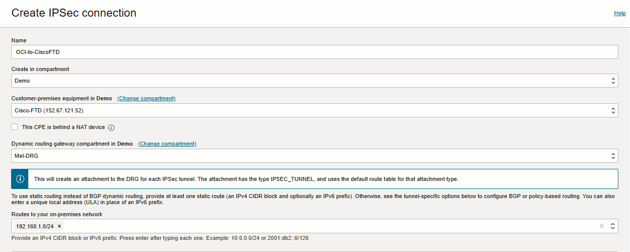
– Create in Compartment: Leave as is (the VCN’s compartment).
– Name: Enter a descriptive name for the IPSec connection.
– Customer-Premises Equipment Compartment: Leave as is (the VCN’s compartment).
– Customer-Premises Equipment: Select the CPE object that you created earlier, named Cisco-FTD.
– Dynamic Routing Gateway Compartment: Leave as is (the VCN’s compartment).
– Dynamic Routing Gateway: Select the DRG that you created earlier.
– Static Route CIDR: Input static routes representing your on-prem CIDR block(Example:192.168.1.0/24).Up to 10 static routes
can be configured for each IPsec Connection.
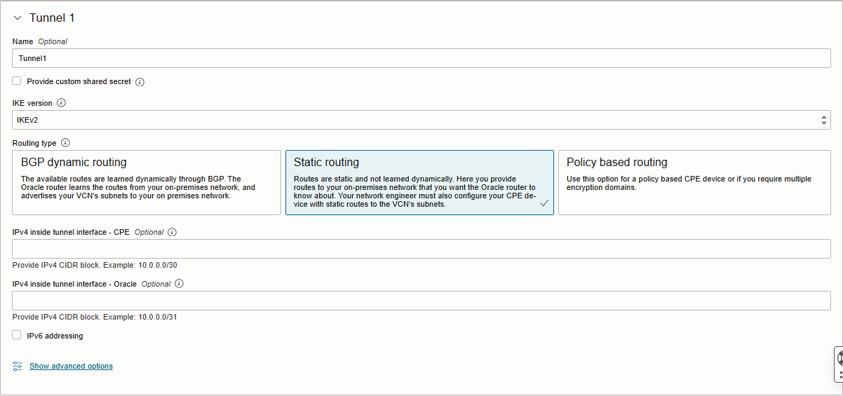
Enter the following details on the Tunnel 1 tab (required):
– Name: Enter a descriptive name for the tunnel (Example: Tunnel1)
– Provide custom shared secret: The pre-shared key used by IPSec for this tunnel. Select this checkbox if you would like to use
a custom key. If left unselected one is generated for you.
– IKE Version: Select IKEv2.
– Routing Type: Select Static Routing.
– IPv4 Inside Tunnel Interface – CPE: Optional (I left it blank)
– IPv4 Inside Tunnel Interface – Oracle: Optional (I left it blank)
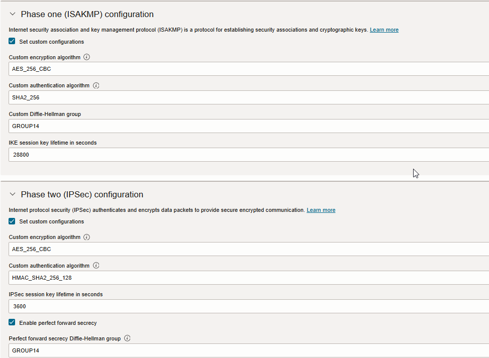
Click Show advanced options and Expand Phase One and Phase Two (IPSec) Configuration if you would like to use a custom
ISAKMP and IPSec configuration.
Note: Please check my custom configurations below.
Click Create IPSec Connection.
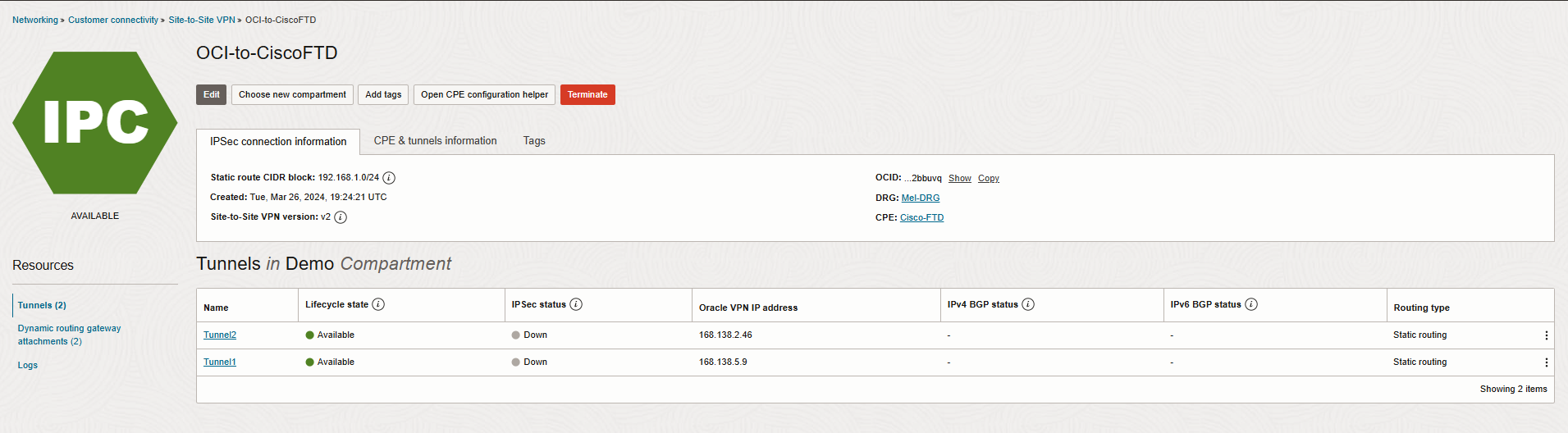
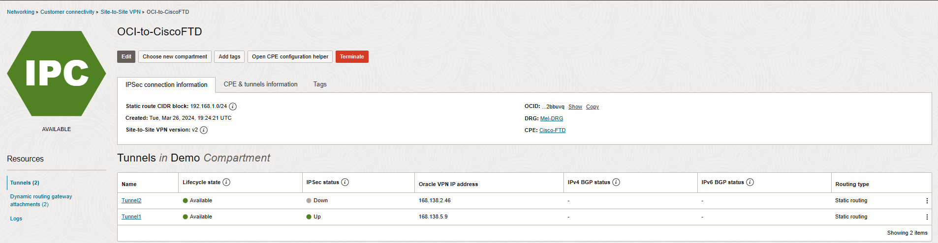
The IPSec connection is created and displayed on the page. The connection is in the Provisioning state for a short period. Now, click on Open CPE configuration helper, create content, and download configuration.
Note: You need to save the Oracle public IP address, and Shared secret.
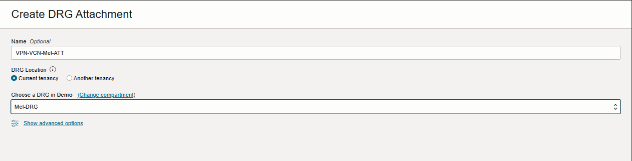
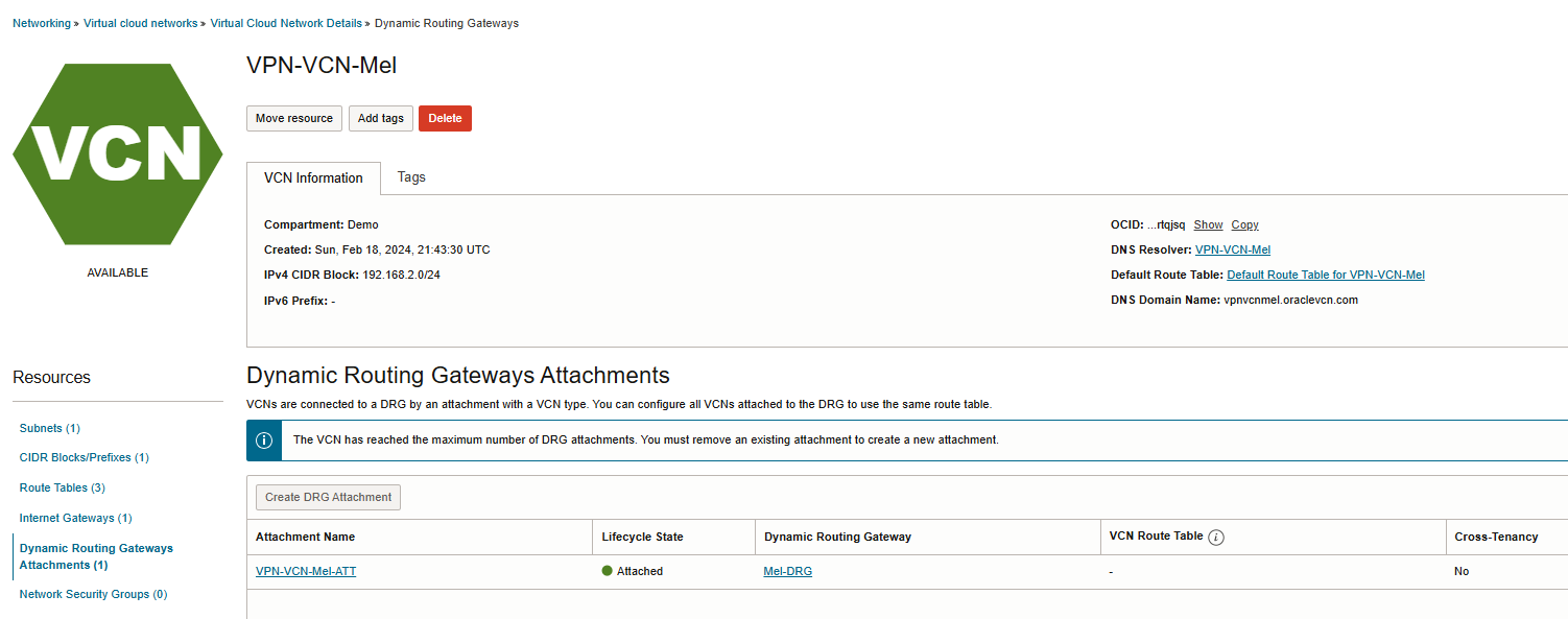
 For the last step, navigate to Networking-> Virtual cloud network -> Virtual Cloud Network Details-> Dynamic Routing Gateway Attachments-> Create DRG Attachment.
Create VPN Connection
1. Connect to your Cisco FMC.
2. Navigate to Devices -> VPN -> Site To Site VPN.
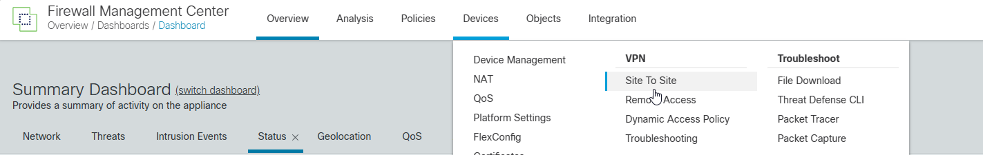
3. Select + Site to Site VPN to add a new IPSec VPN connection.

Most of the configuration will be under the Create New VPN Topology section. However, prior to configuring the VPN Topology section, we’ll need to define the ISAKMP and IPSec Policy that will be used by phase 1 and phase 2 of the IPSec connection.
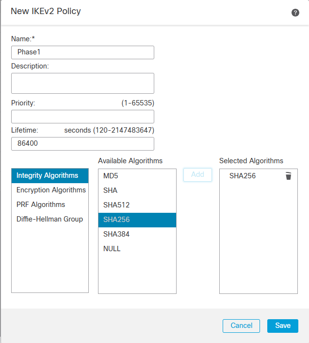
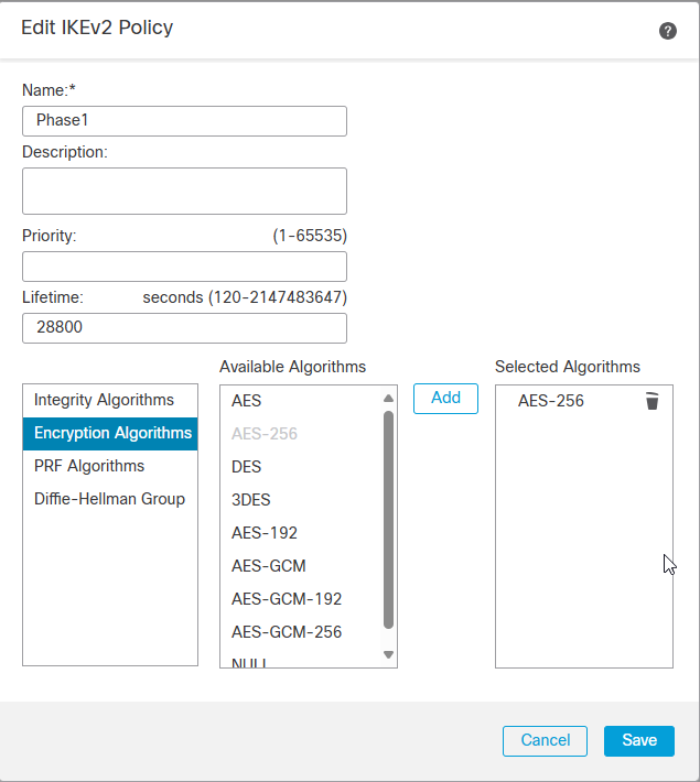
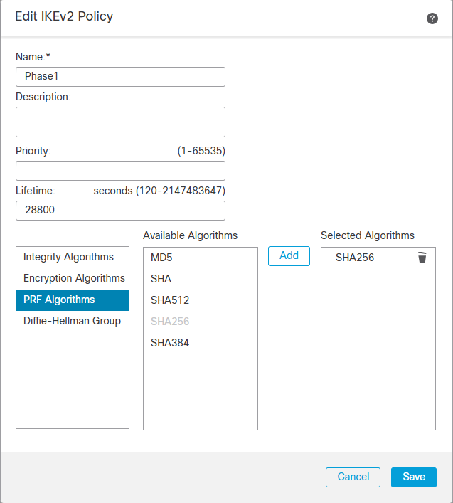
To configure the IKE and IPSec Policy, we’ll need to navigate to the Objects -> Object Management -> VPN.
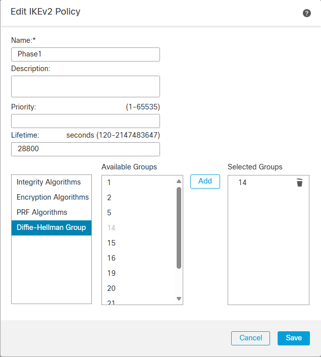
Depending on which version of IKE you are using, you will need to create the proposals for the respective IKE version. In my case, I am using IKEv2 and will use the IKv2 Policy and IKEv2 IPsec Proposal to manage the cipher suites.
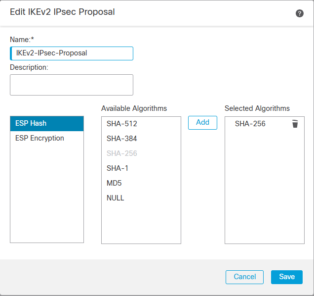
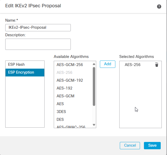
IKEv2 IPSec Proposal
Let’s Navigate to Devices -> VPN -> Site To Site VPN.
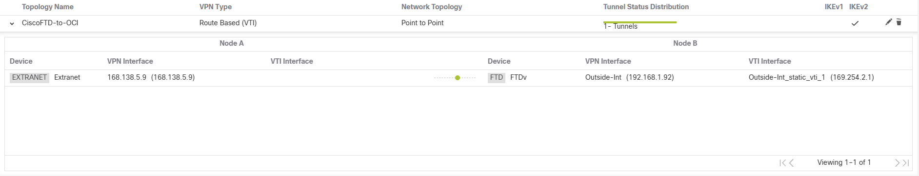
Create New VPN Topology
Please check the screenshots below.
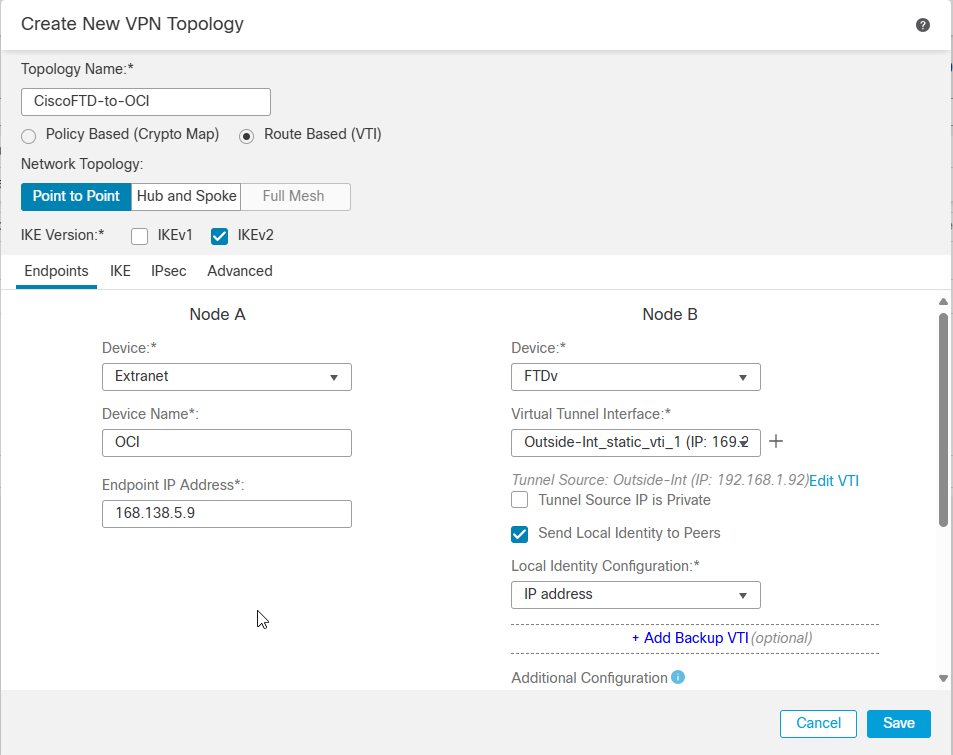
Note: Node A is an extranet device (OCI) and Node B is FTD.
Note: 168.138.5.9 is Oracle Tunnel1 public IP address.
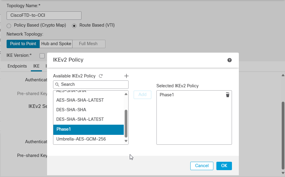
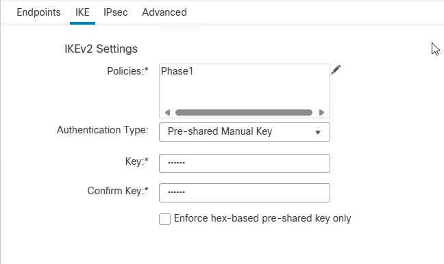
Click on IKE tab and select the existing IKEv2 Policy we created earlier.
Click Ok, choose Pre-shared Manual key as an Authentication Type and match key with OCI side.
(Refer to the downloaded configuration document from OCI).
Now, move to the IPsec config tab to select custom created IPsec policy.
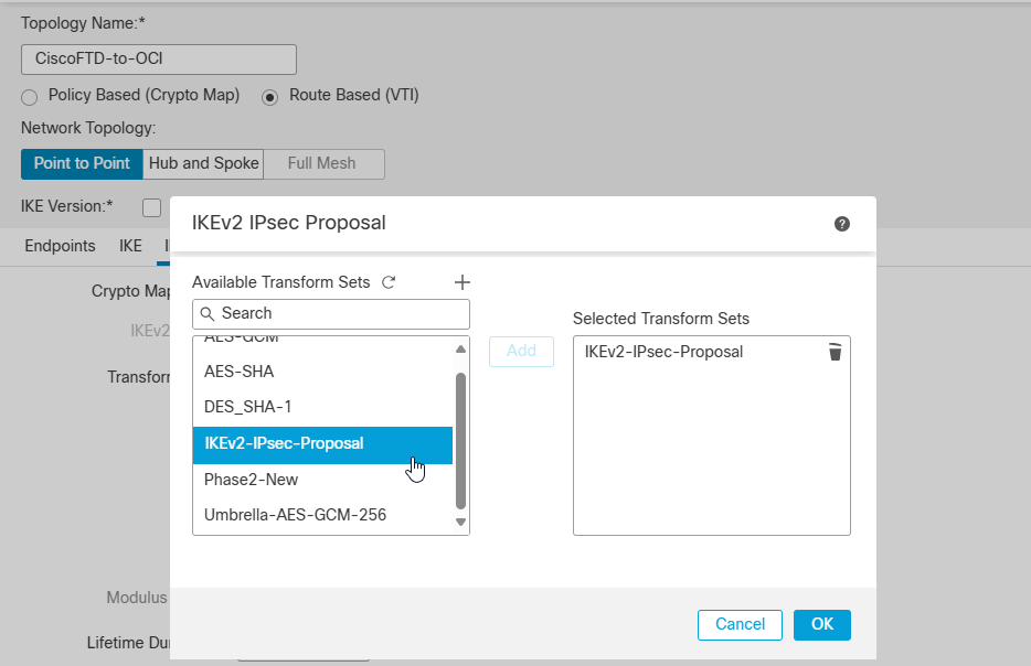
Click Ok and Save.
At this point you should see the tunnel status is Active and Up.
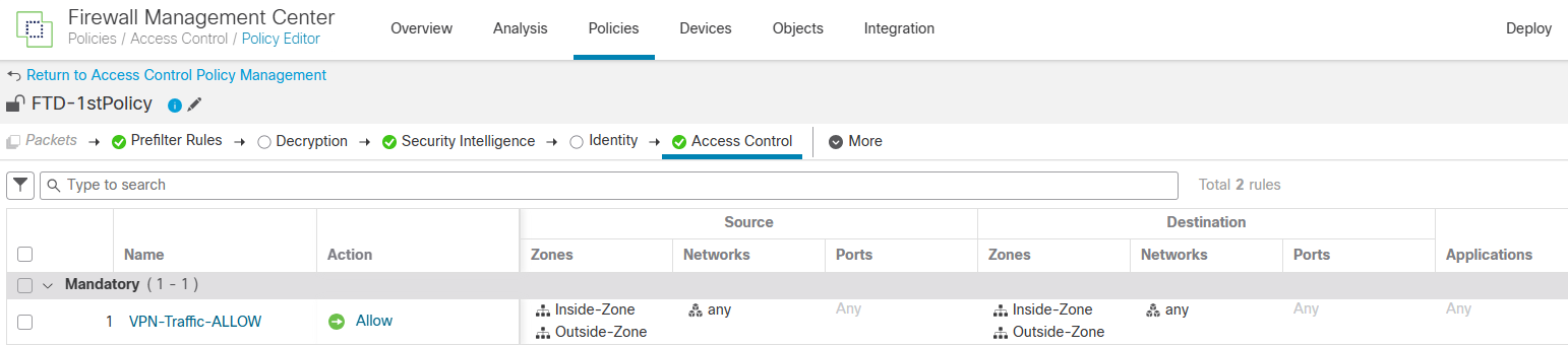
Note: Please before adding a static route to confirm a connection, ensure you have configured proper policies within FTD to allow VPN traffic and OCI VCN CIDR block.
For blogging purposes, I allowed any networks to any networks from the Access Control configuration. Check the screenshot below.
Configure Static Routing
Navigate to Devices -> Device Management -> FTD -> Routing -> Static Route -> + Add Route.
First Route: Default route via the outside interface.
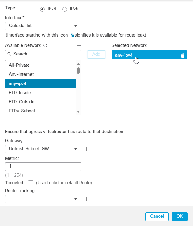
Note: Click on any-ipv4 (0.0.0.0/0 Default Route).
Note: In my case, gateway is the first IP address of Cisco FTD outside Interface IP address CIDR Block.(Untrust-Subnet-GW: 192.168.1.65)
Second route: The OCI VCN CIDR block ( The VCN is already attached to DRG with VPN connection) via the vti Interface.
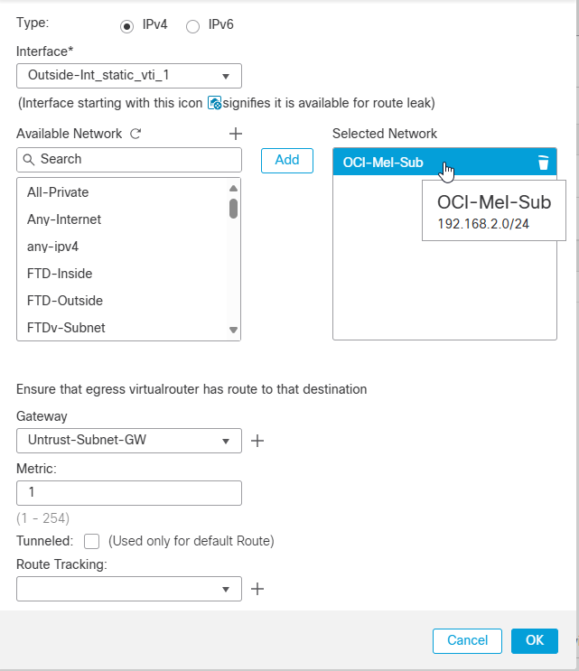
Note: I created a route to OCI Melbourne region where I have created VPN connection and test VM to confirm a connection.
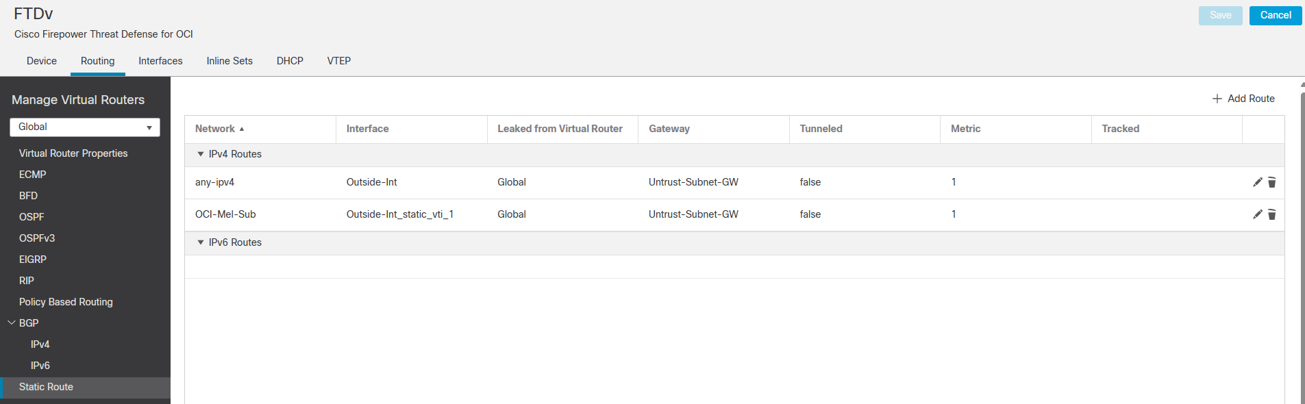
Note: After saveing the new added routes don’t forget to Deploy a configuration.
Here is what you have after save your static routes configuration.
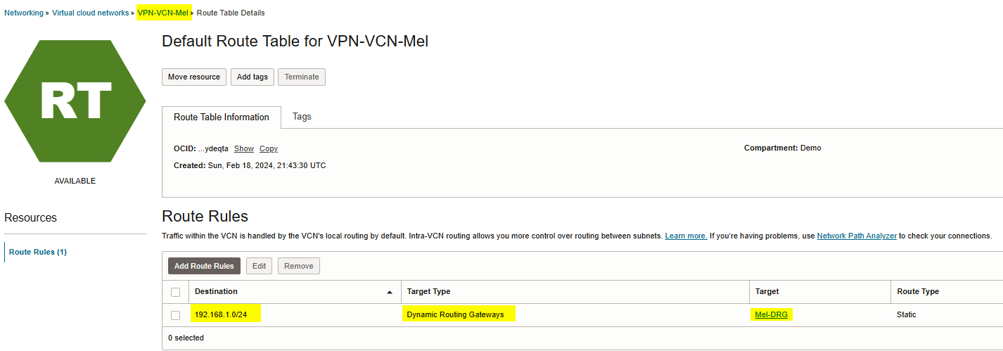
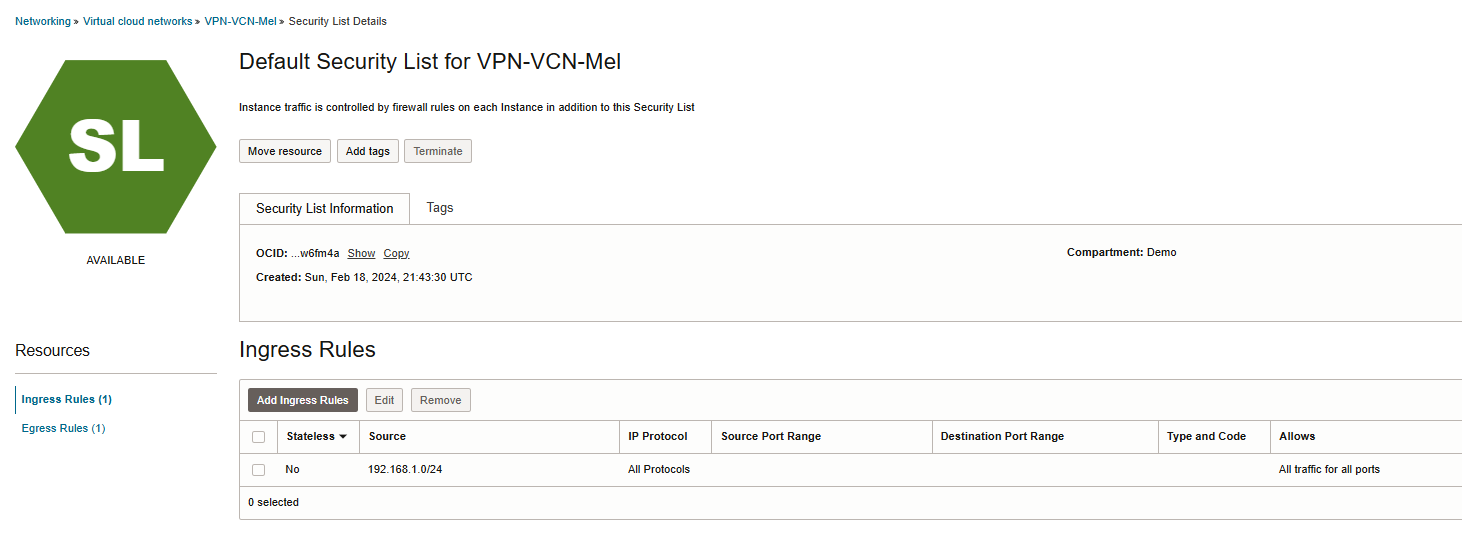
Note: Please ensure you have proper routing configured on OCI VPN-VCN-Mel routing table.
192.168.1.0/24 is an on-prem network.
Note: Please ensure you have configured proper policy to allowing ingress traffic from on-prem to OCI.
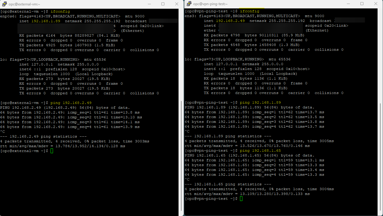
Verification
Let’s check the VPN tunnel status from Cisco and OCI.
 I also created a VM( 192.168.2.49) on OCI Melbourne region and test a connection to Cisco firewall outside
interface gateway(192.168.1.65) and VM(192.168.1.89) on-prem. Please check the Screenshot below.
I hope you enjoyed it!