In some of my previous blogs, I presented some OCI to Azure Interconnect scenarios and deployment guides. If you missed them, take a look:
OCI-Azure Interconnect advanced scenarios – part1
OCI-Azure Interconnect advanced scenarios – part2
But what if we wanted private connectivity between these two Clouds and we don’t require that much bandwidth, latency, and so on? Well, the next best choice is the good old IPSEC. The thing is we could be ok with less bandwidth, maybe some spikes in latency (the Internet is after all, best effort) but what we can’t afford to miss is redundancy. Let’s see what redundancy options we have and even do a demo on one of them.
Cloud IPSEC
Let’s first start with a small overview of the IPSEC/VPN service from each cloud.
OCI:
- OCI works with the concept of Site-to-site VPN
- Each VPN you deploy consists of TWO IPSEC tunnels that land on different hardware on OCI so you get that much-needed redundancy. To make use of this redundancy you need to use both tunnels or if that is technically challenging for your CPE, deploy a second VPN and use a tunnel from there as the backup
- All VPN/IPSEC tunnels have a logical endpoint in our Dynamic Routing Gateway
- Related to routing, both static and dynamic are supported and, of course, dynamic (BGP) is always recommended
Azure:
- Azure will deploy one single ISPEC tunnel per remote CPE. If you want redundancy you will need to deploy a second tunnel
- The endpoint in Azure is the Virtual Network Gateway. When we discuss redundancy and features, these are provided by the various VPN GW SKUs and deployment configurations.
- Both routing options are available (static/dynamic)
- One important thing to note is the deployment mode active-passive vs active-active for the Gateway; with active-passive, there is one active node in one Availability domain and, if something happens to that AD, all tunnels are migrated to the backup node in a different AD. With active-active, you get two active nodes (one in each AD) so you get two Public IPs and you need to create IPSEC connections to both endpoints.
There are multiple things we can discuss when comparing the IPSEC offering of each Cloud but that would take too much space in this blog. In general, a single IPSEC connection between the 2 CSPs would look like this:
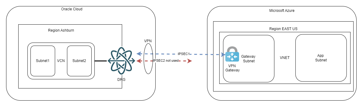
The guide deploying this can be found in Oracle’s documentation here.
When doing this scenario, remember these highlights:
- The default IPSEC parameters of each Cloud are mismatched, related to PFS especially, meaning you need to go into advanced options and input matching parameters
- When using BGP (highly recommended) you need to leverage the “Custom Azure APIPA BGP IP address” option of the VPN Gateway of Azure; if you’re wondering what’s that, it’s a secondary private IP you configure on the Gateway to use for BGP peering. The primary IP of the Gateway is a random IP from the Gateway Subnet which can be used on point to point links only in certain scenarios and will not work for OCI
So, by following the guide above, you will get one IPSEC connection between the 2 CSPs. Now let’s move on to the topic of this blog – IPSEC redundancy.
IPSEC redundancy
When talking about creating secondary links for redundancy we need to split the discussion on the type of routing.
Also, please visit Azure’s documentation related to various redundancy options: vpn gateway highlyavailable.
1.Static routing
While the focus of this blog will be BGP, it is important to note you can have redundancy with static routing. The fact is BGP brings so much more to the table, that doing static routes makes little sense unless you have some corner case.
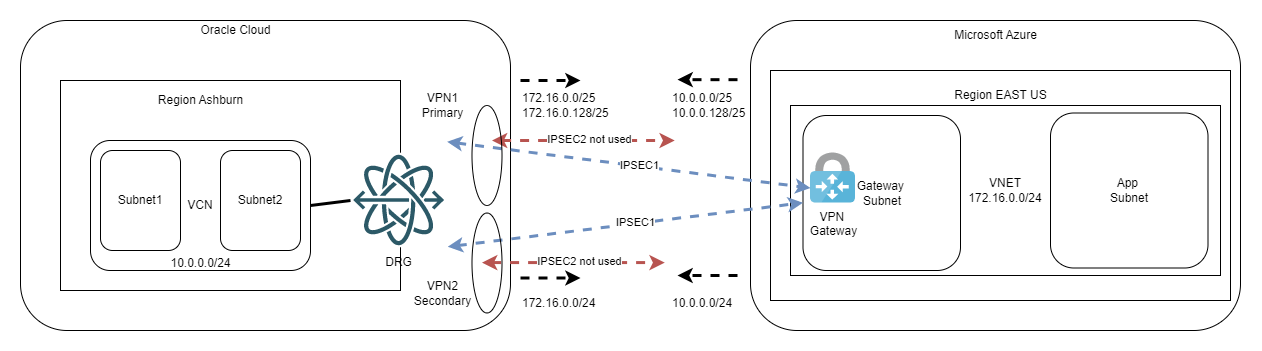
Doing redundancy with static routing looks like this:
- You split the CIDRs of both clouds into half and you put static routes for those on the primary IPSEC tunnel;
- You target the full CIDR with a static route on the secondary (backup) tunnel.
The diagram would look like this:
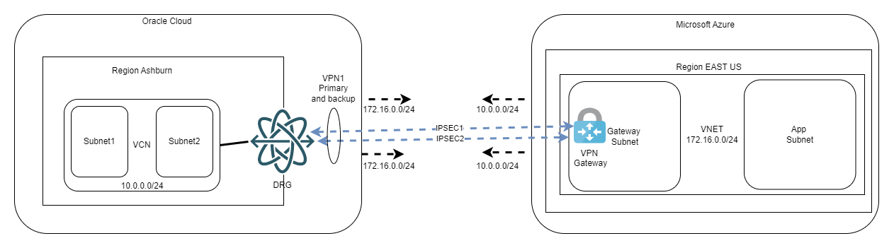
One very important note here: we do this workaround with subnets because we want to decide which tunnel is primary and which is secondary. From OCI’s point of view, you could have the same subnet length on both connections, and everything would work as we fully support asymmetric routing. However, on Azure’s documentation (see link above), it is stated that if the same remote subnet is reachable on two IPSEC tunnels you are required to use BGP and ECMP. While doing my tests I did note it works without BGP, however, I cannot recommend putting in production something that the provider does not support (in the documentation). Just for completeness, the diagram would look like this:
Both diagrams above refer to a Virtual Network Gateway deployed in the active-passive mode. For active-active, you simply double the number of connections, like below:
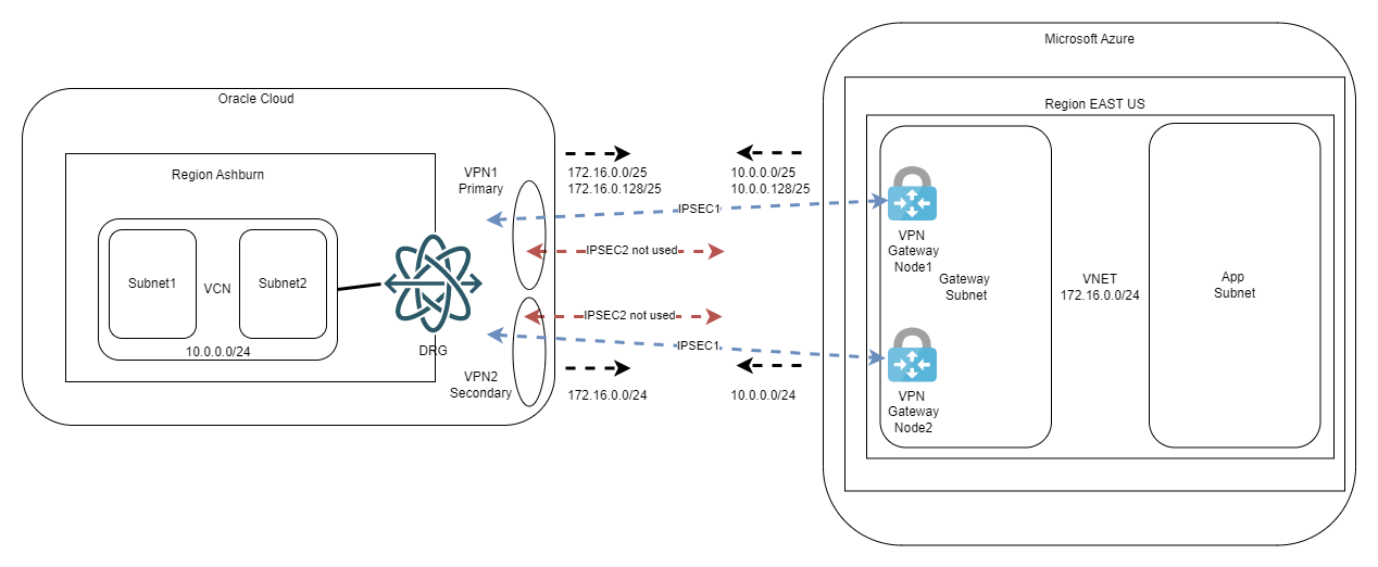
Again, you can always give it a try and bring the second IPSEC tunnel from each OCI VPN online but remember to enable ECMP on OCI VCN DRG Route Tables.
2.Dynamic routing
Before presenting the redundancy scenarios I want to tell you why you should always use BGP if it’s available. BGP brings 2 important things to the table:
- It advertises the CIDRs dynamically. You set things up, 6 months from now you add an OCI VCN for new workloads and everything works, all the routing will update automatically and Azure will learn the new subnets.
- BGP has “keep alive” packets. When using static routes, the control plane relies on “tunnel status” to use the static route or not. There are rare occasions when the tunnel is UP but traffic will not work for various reasons. This will prevent the control plane to reroute to the secondary tunnel and everything stops. With BGP, the keep alive will bring the peer down and the rerouting will happen seamlessly.
For BGP redundancy scenarios, the service that dictates the architecture is the Virtual Network Gateway in Azure. The VNG can be deployed in active-passive and active-active modes. Let’s cover the differences:
a.Active-Active:
- The VNG has 2 active nodes, each with its own Public IP. So, from OCI’s point of view, we are targeting two remote CPEs
- In this deployment mode the VNG supports multiple APIPA IPs (secondary IPs used for P2P links). As OCI will create two VPNs (to target the two IPs of the VNG), this translates to 4 IPSEC tunnels. Considering OCI needs the BGP peer of each tunnel to be configured on the P2P interface, we will need 4 APIPA IPs, one for each IPSEC tunnel.
The high-level diagram would look like this:
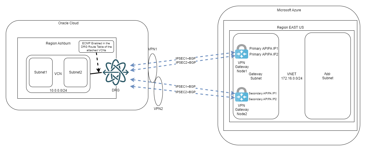
We are also required to enable ECMP, as per Microsoft’s documentation. This design will give you the maximum redundancy and the maximum throughput as all 4 tunnels will be used at the same time. To put it simply, this is the best architecture you can achieve for this type of connection.
b.Active-Passive:
- The VNG has 1 single Public IP assigned to the active node. The second node (which lives in a different AD) acts like a standby and does not participate in the traffic as long as the primary is alive
- In this deployment mode the VNG supports a single APIPA IP (secondary IP used for P2P links).
More info on Azure APIPA IPs on the VNGs here: https://learn.microsoft.com/en-gb/azure/vpn-gateway/bgp-howto#2-create-the-vpn-gateway-for-testvnet1-with-bgp-parameters
Note: While the Azure Portal does allow you to put multiple APIPA IPs on the Virtual Network Gateway, if the VNG is in active-passive mode it will only allow BGP to establish with the first IP you input.
As stated above, the VNG can have only one APIPA IP so we need to find a way to define two BGP sessions where OCI has two different IPs targeting the same Azure VNG. As these are point to point links we will need to get creative. OCI supports both /30 and /31 on the point-to-point tunnels so we will leverage that to go around the limitation. In the end, the diagram will look like this:
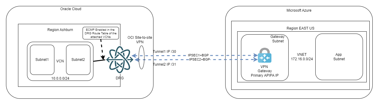
We will also enable Equal Cost Multi-Path so we can use both tunnels at the same time. This will double the available bandwidth on top of the redundancy we already get.
Final note
In this blog we looked at some architectures for IPSEC connectivity between the Oracle Cloud and Microsoft Azure. Now let’s jump to part 2 of this topic and look at a step-by-step guide on how to implement the last scenario (BGP redundancy with active-passive Virtual Network Gateways).
