Prerequisite
Routing configuration for multiple routing domains – part 1
In the Part 2 of the blog dedicated to multiple routing domains we will analyze the DRG configuration for the traffic to flow and inspected based on the points we highlighted in Part 1.
We will use the same networking topology:
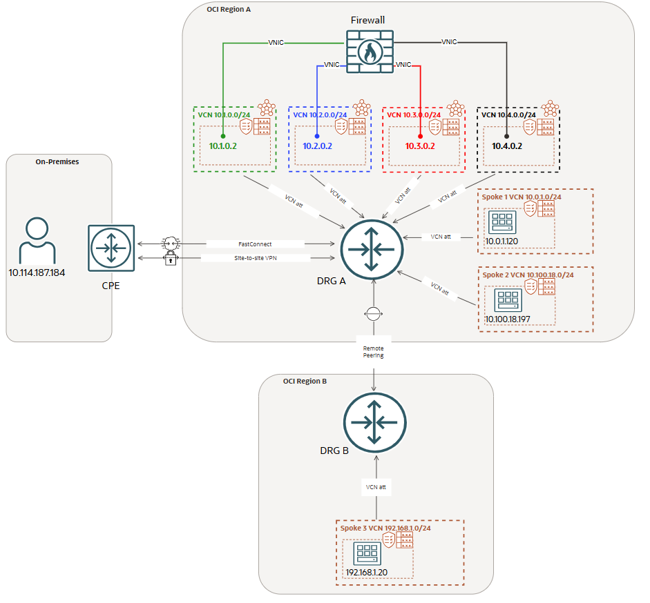
DRG attachments route tables and DRG VCN route tables (for transit routing)
The FastConnect or IPSec DRG attachment route table will contain only static routes to Spoke1/2/3 with the Green VCN as next-hop attachment:
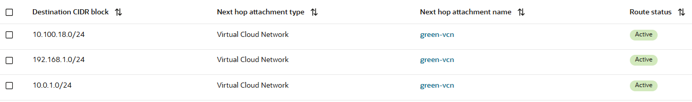
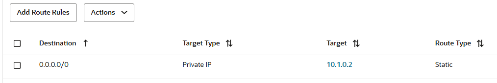
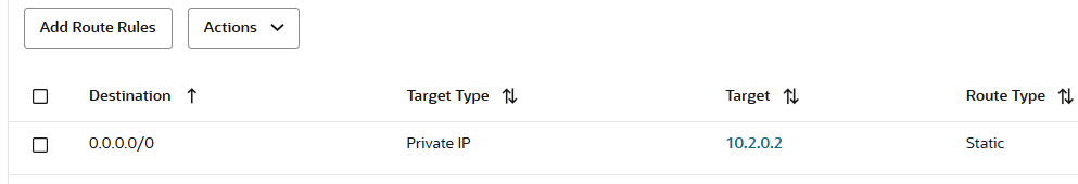
All the traffic that is initiated from On-premises to any of the Spoke VCNs, needs to be received by the green Firewall interface at 10.1.0.2. The transit routing DRG green VCN route table that will be used has the following entry:
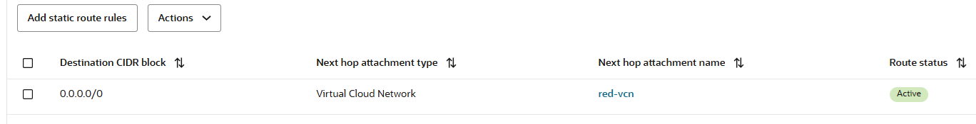
The RPC attachment route table will contain only a static routes to 10.0.0.0/8 (it can be also specific) with the Blue VCN as next-hop attachment:
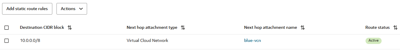
All the traffic that is initiated from OCI Region B to OCI Region A Spoke VCNs or to On-premises, needs to be received by the blue Firewall interface at 10.2.0.2. The transit routing DRG blue VCN route table that will be used has the following entry:
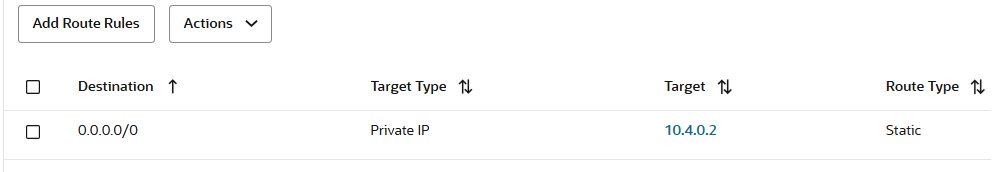
The DRG Spoke 1 VCN attachment route table will contain only a static default route with the Red VCN as next-hop attachment:
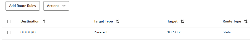
All the traffic that is initiated from Spoke 1 VCN to other Spoke VCNs or to On-premises, needs to be received by the red Firewall interface at 10.3.0.2. The transit routing DRG red VCN route table that will be used has the following entry:
The DRG Spoke 2 VCN attachment route table will contain only a static default route with the Balck VCN as next-hop attachment:
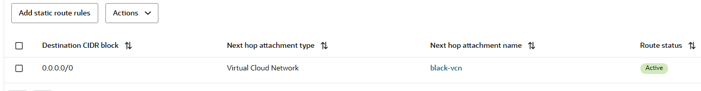
All the traffic that is initiated from Spoke 2 VCN to other Spoke VCNs or to On-premises, needs to be received by the black Firewall interface at 10.4.0.2. The transit routing DRG black VCN route table that will be used has the following entry:
The DRG Green, Blue, Red and Black VCN attachments will share the same route table and will dynamcally import by using the Import Route Distribution: Spoke1/2 VCNs, RPC and FastConnect or IPSec attachments. We should have the following dynamic imported routes:

The DRG is prepared now to forward the traffic based on the routing domains defined. For each direction of the traffic, the DRG will use a specific firewall interface as ingress interface. That will be the security inspection point for that flow.
Even if the DRG has all the intelligence we need based on the configuration applied, we still need to instruct the Firewall how to forward the traffic after it is inspected. This means we just need to define the traffic egress interfaces by configuring the internal Firewall routing policies.
Firewall routing configuration
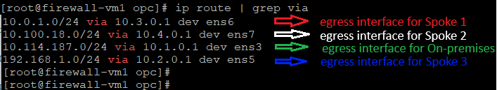
The Firewall used in our test environment is a Linux VM with IP Forwarding function activated. The routing configuration will define the egress interfaces that needs to be used for different destinations.
We have configured the following route entries:
Now, we have all the routing configuration in place so, let’s test the traffic and verify if the desired Firewall interfaces are correctly used.
Routing domains traffic testing
In the current section we will test the traffic on the following routing domains (the tests will use ICMP and a dual packet capture on the ingress/egress Firewall interfaces assigned to that routing domain):
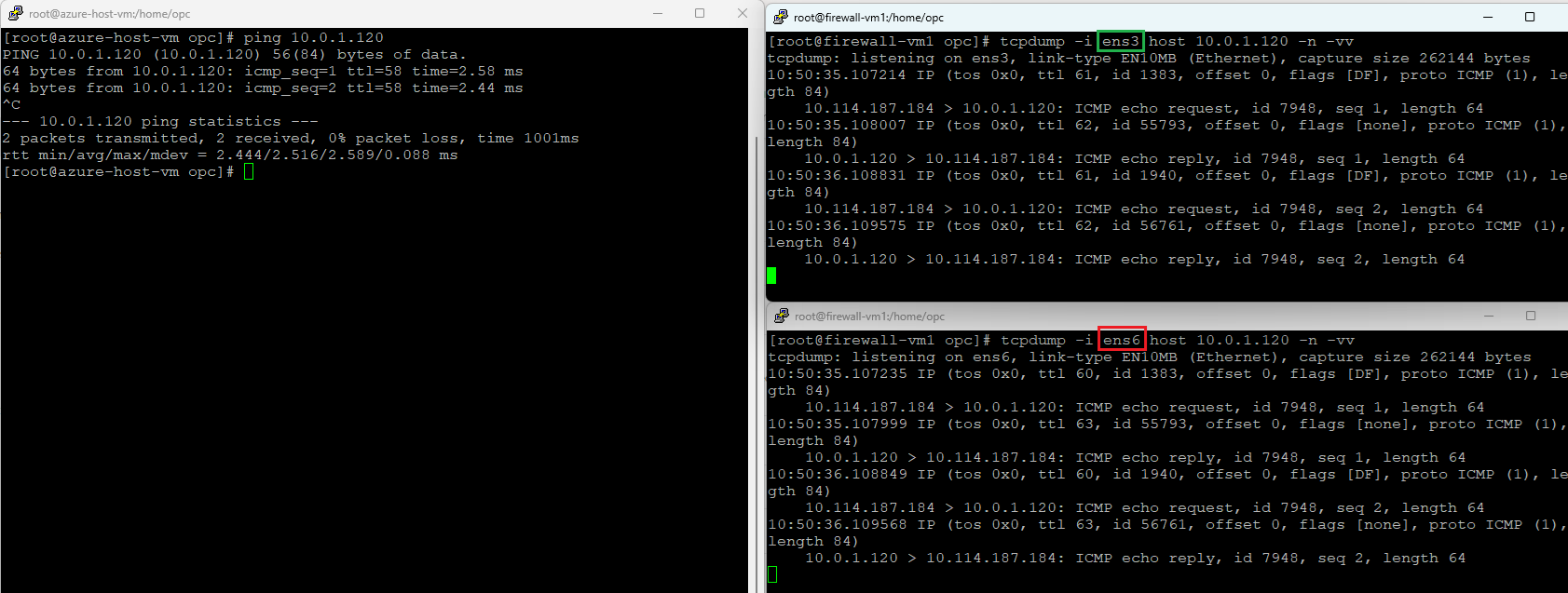
1. On-premises (10.114.187.184) to Spoke 1 (10.0.1.120)
Ingress interface – green (ens3)
Egress interface – red (ens6)
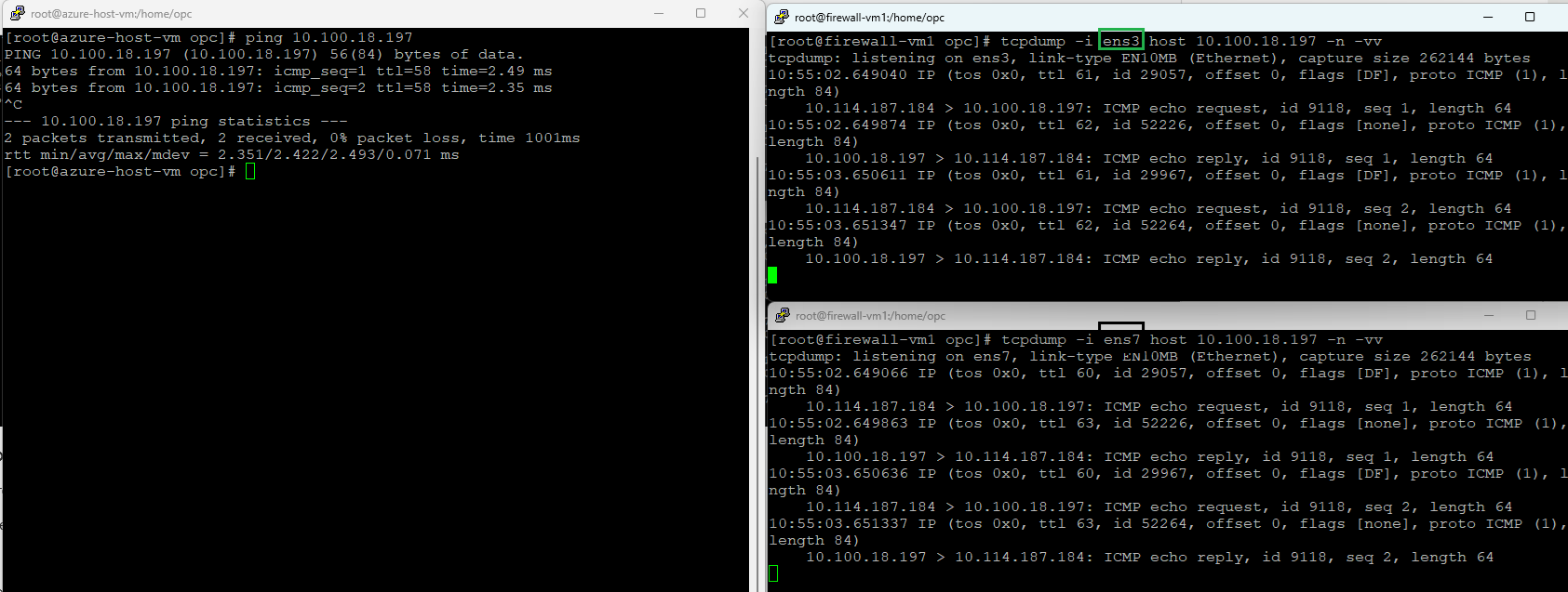
2. On-premises (10.114.187.184) to Spoke 2 (10.100.18.197)
Ingress interface – green (ens3)
Egress interface – black (ens7)
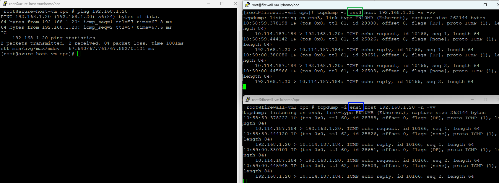
3. On-premises (10.114.187.184) to Spoke 3 (192.168.1.20)
Ingress interface – green (ens3)
Egress interface – blue (ens5)
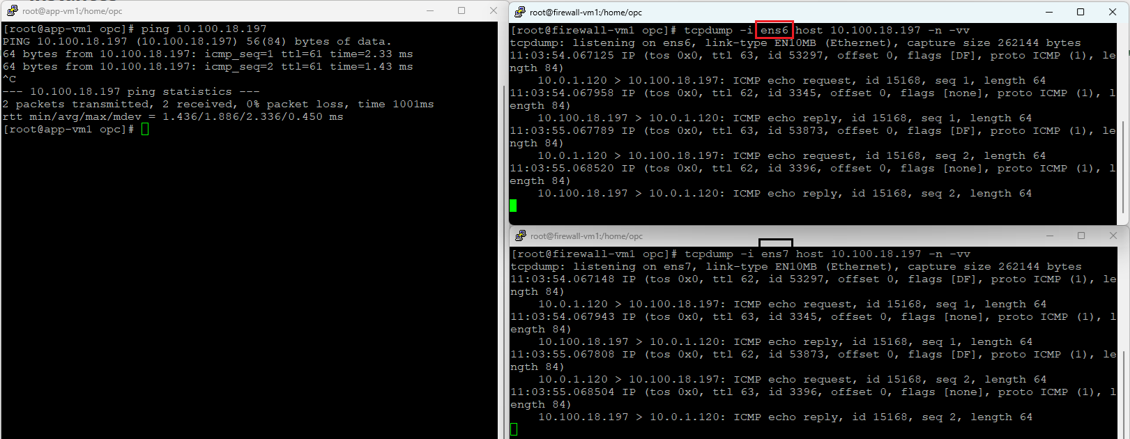
4. Spoke 1 (10.0.1.120) to Spoke 2 (10.100.18.197)
Ingress interface – red (ens6)
Egress interface – black (ens7)
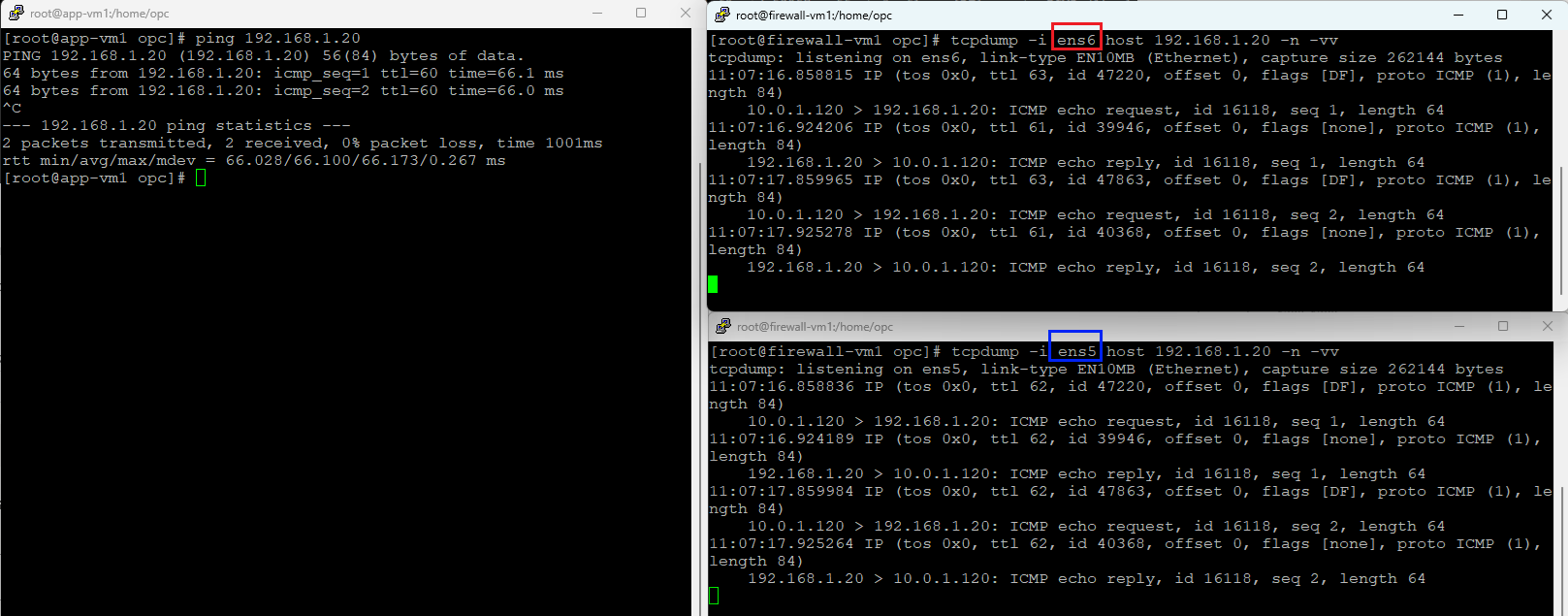
5. Spoke 1 (10.0.1.120) to Spoke 3 (192.168.1.20)
Ingress interface – red (ens6)
Egress interface – blue (ens5)
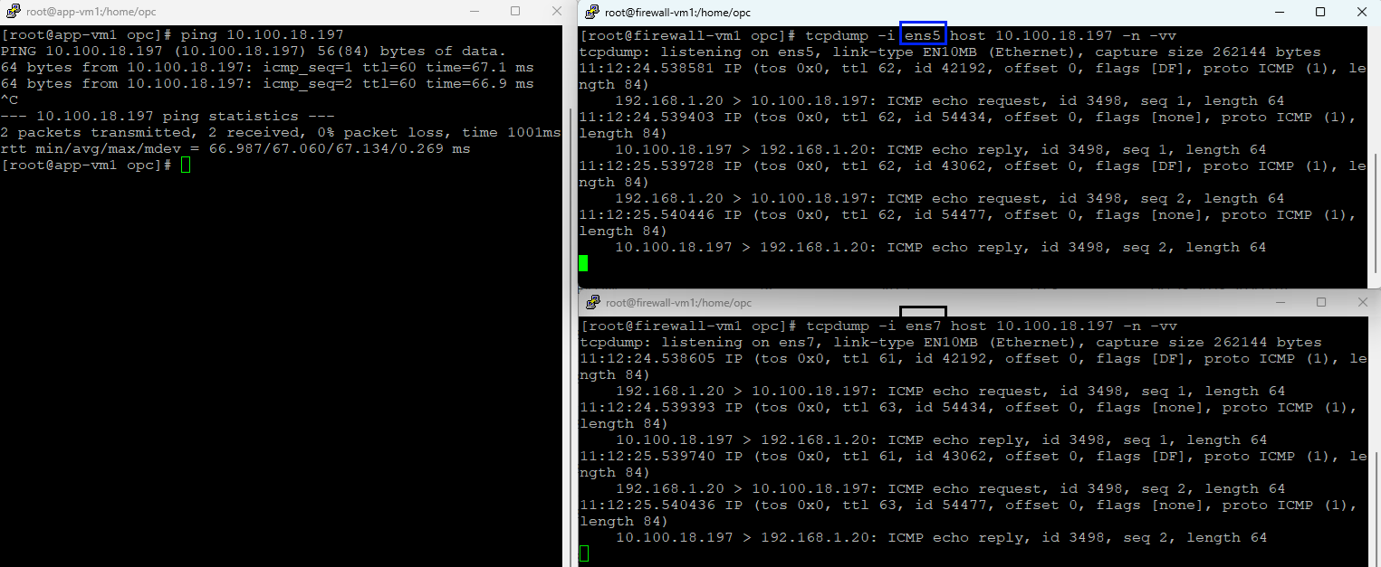
6. Spoke 3 (192.168.1.20) to Spoke 2 (10.100.18.197)
Ingress interface – blue (ens5)
Egress interface – black (ens7)
You may ask, what about TCP traffic, is that working correctly in this scenario? Let’s find out:
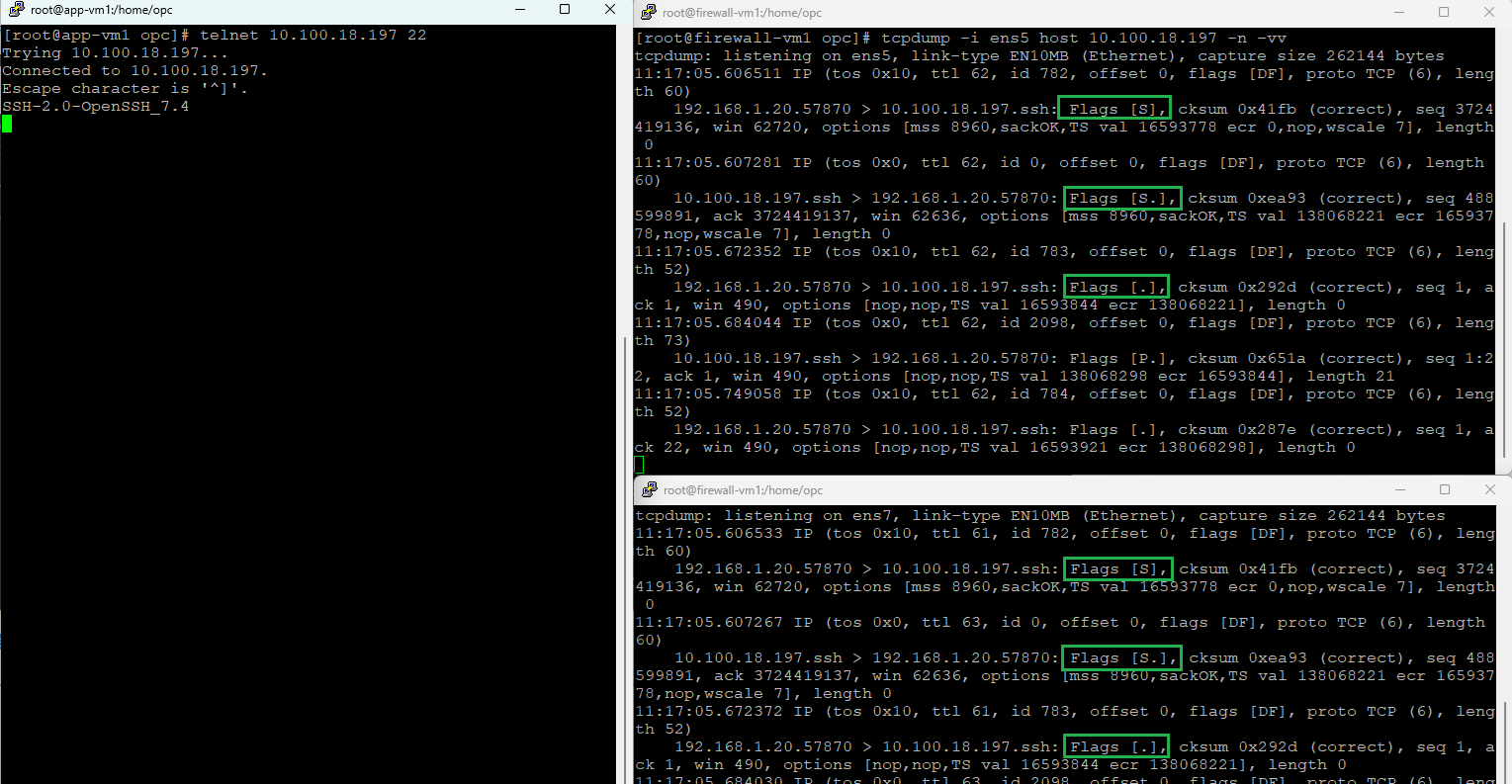
Definitively, the TCP traffic is working as expected. We do not have any asymmetric traffic in our networking topology and this will assure that once the network will accommodate more and more services, the traffic will flow just as expected.
Conclusions
On OCI we can build some of the most advanced networking configuration. The use case presented in this two part blog confirms that using the DRG powerful routing engine, together with the internal networking and security, we can create some of the most advanced networking scenarios for our customers.