

Introduction
Oracle Cloud Infrastructure (OCI) FastConnect provides private connectivity between customers’ networks and OCI. Megaport extends FastConnect reachability to Megaport-enabled data centers through its software-defined network, allowing customers to provision connections without building a physical presence at every Oracle interconnection point.
For critical workloads, it is essential to have redundancy and diversity of connectivity between OCI and a customer’s enterprise network. Redundancy provides multiple network paths. Diversity is the separation of network paths across distinct devices, locations, and infrastructure such that a single failure cannot disrupt all paths. Deploying multiple FastConnect virtual circuits is the first step towards this goal but is not sufficient by itself. The circuits may still share single points of failure such as a common customer router, common Megaport-OCI on-ramp, common Megaport diversity zone, common Megaport Cloud Router (MCR), and so on.
In this blog, we will discuss how diversity can be achieved for redundant connections, when using Megaport as a FastConnect partner. The blog will be using the following terms extensively and the reader can refer to the links for a better understanding of these terms:
- Megaport Port
- Megaport Diversity Zones
- Megaport Virtual Circuit (VXC)
- Megaport Cloud Router (MCR)
- OCI FastConnect
- OCI Dynamic Routing Gateway (DRG)
Scenarios
Megaport as Layer 2 Transit
In this scenario, Megaport is used as a transit medium which provides layer 2 connectivity between OCI and a customer’s datacenter. BGP sessions terminate on the customers’ equipment in their data centers.
1. Connectivity between a single OCI region and a single customer data center
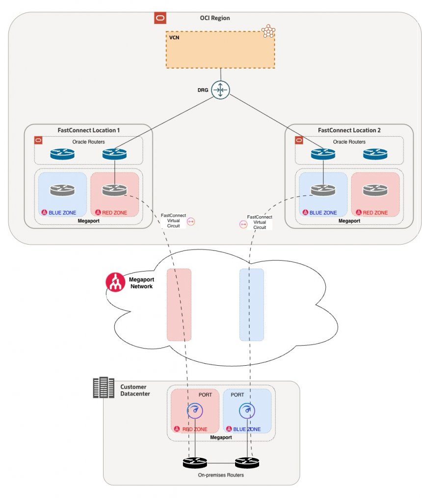
This design can be used when connecting a single OCI region to a single data center. Both FastConnect virtual circuits terminate on the same Dynamic Routing Gateway (DRG).
OCI-side Configuration
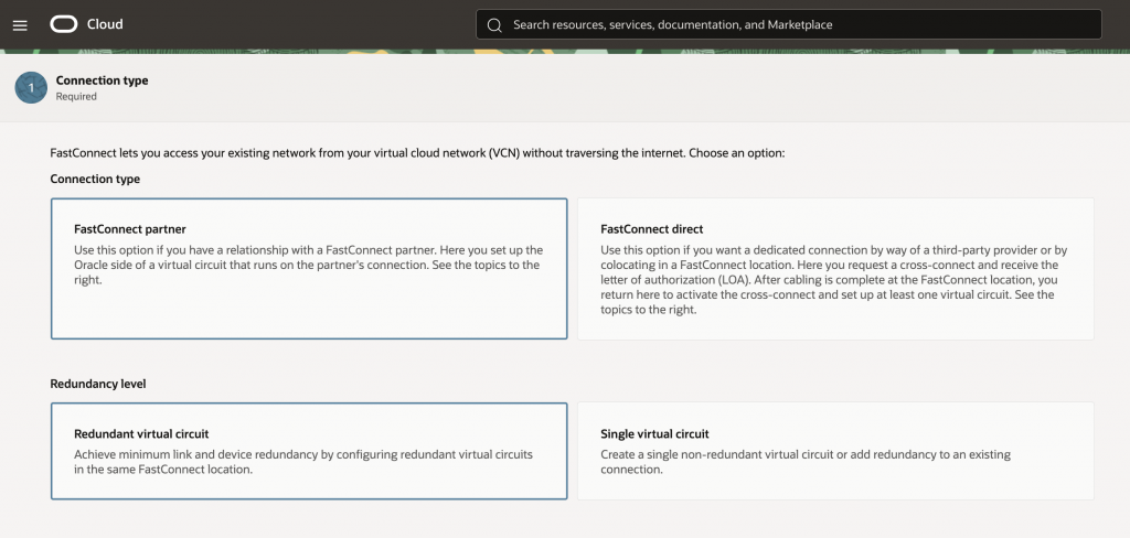
When configuring the FastConnects in the OCI Console, customers should deploy them as partner interconnects with redundant FastConnect circuits. For each virtual circuit, select ‘Megaport:Service’ as the partner and enter unique BGP peering addresses. Both virtual circuits will terminate on the same DRG but different logical devices. This will allow you to setup either as Active-Standby using BGP attributes or enable ECMP. Note down the OCID for each virtual circuit.
On-premises (datacenter) configuration
In the datacenter, a customer should have 2 ports from Megaport, in 2 separate diversity zones such that one is in the red zone, and the other is in the blue zone.
Furthermore, there should be 2 separate devices / routers for terminating the Layer-2 connection and for the BGP peering with OCI, one per FastConnect virtual circuit. Each of these devices should have a separate cross-connect to the Megaport ports, preferably going via separate patch panels.
Megaport-side Configuration
Virtual Circuit 1
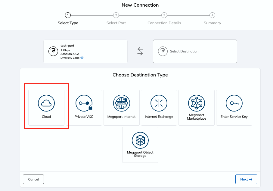
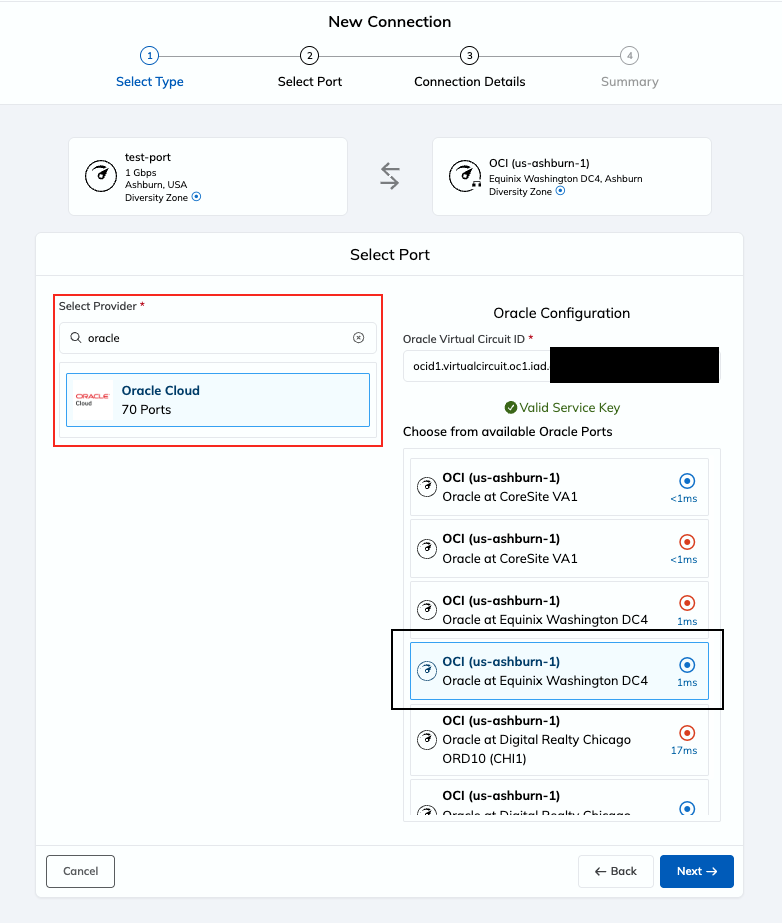
From the Megaport portal, select the first port for the customer datacenter. Assume that this is in the Red Diversity zone. Click on the ‘+’ button for creating a connection (or VXC) and then select ‘Cloud’ and then select ‘Oracle Cloud’
Enter the OCID of the first virtual circuit and select a connection port in the same diversity zone as that of the datacenter port – RED in this case.
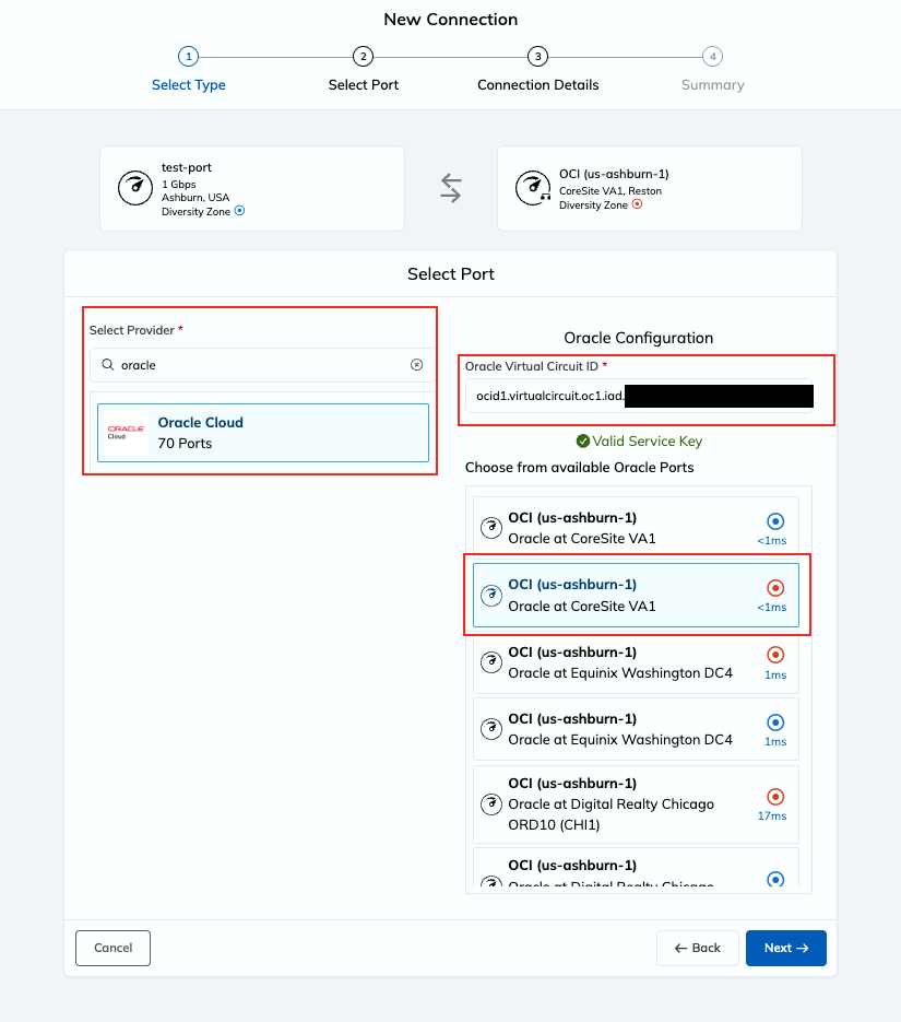
Complete the rest of the configuration for the first virtual-circuit.
Virtual circuit 2
For the second virtual circuit, follow the same steps but select a different Oracle port for the connection. In this case, select an Oracle port in a different diversity zone (BLUE in this example), and you can also select it in a different facility than the one used for the first virtual circuit. In this example, we selected a port in the BLUE diversity zone in the Equinix DC4 facility for the second virtual circuit because the first virtual circuit used a port in the RED diversity zone in Coresite VA1. Complete the rest of the configuration.
2. Connectivity between a single OCI region and multiple customer data centers
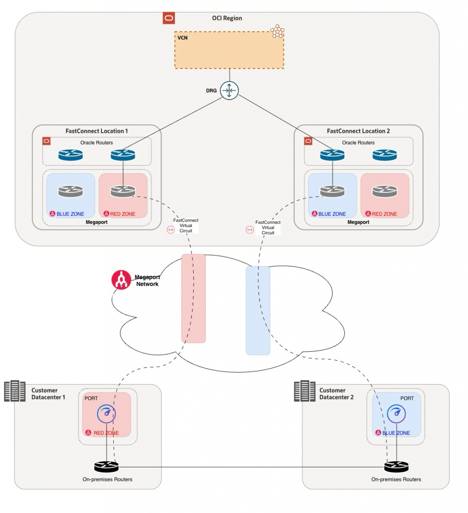
The concept of connectivity between a single OCI region to a single customer datacenter can easily be extended if a customer wishes to connect instead to multiple datacenters. It is assumed that the two datacenters are connected by customer-provided connectivity such as wavelength circuits, MPLS ,VPN etc. For this use case, the customer should purchase a Megaport Port in each datacenter but ensure that they are in two different diversity zones – one RED and the other BLUE.
Thereafter, the connectivity process (configuring FastConnects, creating virtual circuits and selecting on-ramp ports) will be identical to that discussed in scenario 1.
One thing to note when connecting the same region to multiple datacenters is that the latency from OCI to two different datacenters could be different. Depending on the use case, the customer should either opt for an Active-Active routing posture or an Active-Standby posture if the latency is not significant or if it does not affect the underlying use case.
3. Multiple OCI region to single customer datacenter
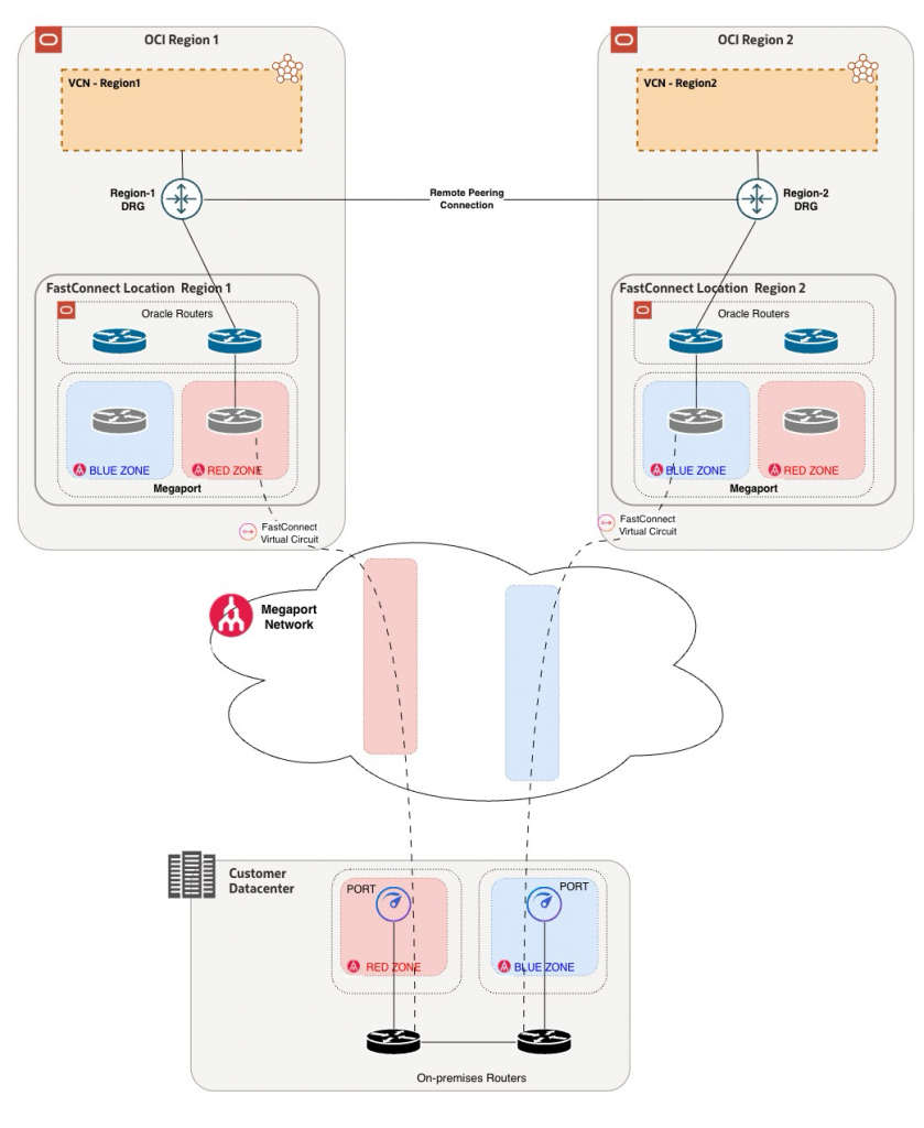
If a customer has a single on-premises facility but is present in two or more OCI regions, they can either deploy dual FastConnect circuits from each region (which would be similar to the first case) or they can deploy a single FastConnect virtual circuit from each region and treat them as backups for those in other regions. In this case, a customer would choose a single FastConnect virtual circuit from each region. These virtual circuits will terminate on separate Dynamic Routing Gateways (DRGs) in their respective regions. Since each virtual circuit is in a different region, they will each be on a different Oracle router anyways. Also, there are similar latency considerations in this option as explained in section 2.
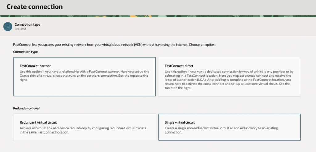
Complete the rest of the configuration for virtual circuits in each region. For the on-premises and Megaport configuration, this is identical to scenario 1.
Complete the rest of the configuration for virtual circuits in each region. For the on-premises and Megaport configuration, this is identical to scenario 1.
Note: As this setup introduces the RPC connection, it needs modification of DRG route tables and import route distributions as the Autogenerated ones do not allow the Virtual circuit traffic by default.
Validation
Validation on the Megaport side can easily be done by confirming that each on-ramp port and MCR reside in different diversity zones. On the OCI side, once configuration is completed and BGP peering is up for both, we can validate that the OCI side is diverse by verifying the status values on the console.
On the OCI side, once configuration is completed and BGP peering is up for both virtual-circuits, you can validate that the OCI side is diverse using the following tools / status values –
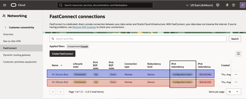
IPv4 Redundancy
The console will confirm that you have IPv4 redundancy as shown in the following image.
Note that the Red and Blue ribbons have been added to the image to highlight the Megaport diversity zones that the virtual-circuits have been terminated on and are not actually visible on the OCI console.
OCI device diversity
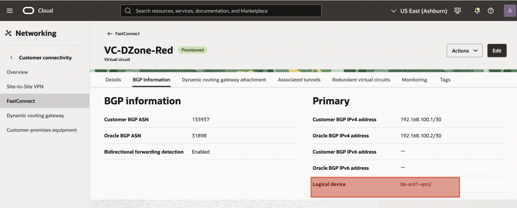
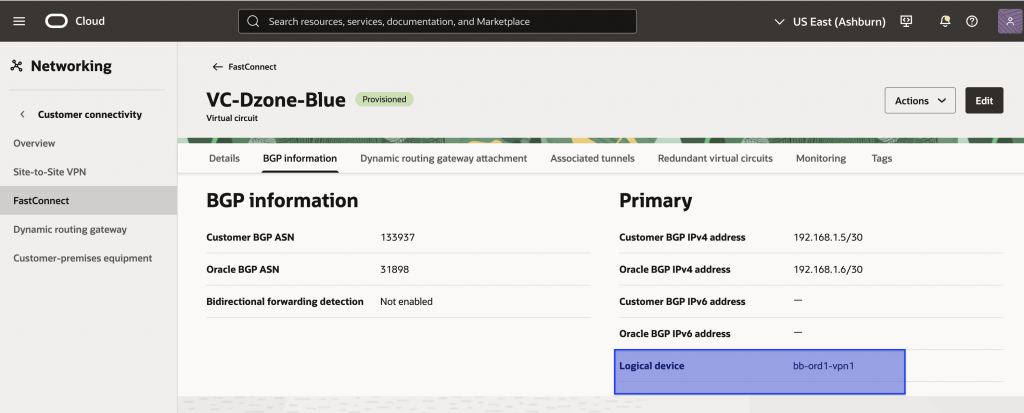
When creating redundant FastConnect virtual circuits, OCI terminates them on different logical devices to provide diversity. This can be verified from the BGP information. As shown below, the RED and BLUE virtual circuits terminate on different OCI logical devices.
DRG overall redundancy status
The OCI Console also provides you with an overall redundancy status for connectivity terminating on your OCI Dynamic Routing Gateway (DRG). This can be seen by navigating to the Dynamic Routing Gateway page of the OCI console as shown below.
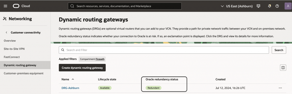
If it shows a value of “Redundant”, it confirms that the customer has multiple paths between OCI and on-premises and that they have been terminated on diverse equipment within OCI and that all are UP and functional. If the value is “Non-Redundant”, either the paths are not diverse or one of them has gone down or there is only a single connection. Customers should validate their network and circuit status and also refer to the Redundancy Remedies document for guidance.
Conclusion
Deploying multiple FastConnect virtual circuits is only the first step toward building resilient OCI connectivity through Megaport. True diversity requires eliminating shared points of failure across on-prem, Megaport, and OCI infrastructure. Careful placement of Megaport Ports, diversity zones, on-ramps, and customer networking equipment helps achieve end-to-end path separation. By considering redundancy and diversity together, customers can build more resilient FastConnect architectures for business-critical workloads.