
Hi! In this blog entry we will talk about extending a VLAN or network from your datacenter to Oracle Cloud Infrastructure with Cisco Catalyst 8000v.
Layer 2 extension to the cloud
Let’s talk about extending your network into the cloud. Cloud native networking is mostly not Layer 2 capable which means that ARP, broadcast, multicast services are not supported in the way a physical network supports them. Because of that, it’s generally a bad idea to extend your broadcast domain/VLAN into the cloud and the recommendation is to deploy your cloud workloads with a new set of IPs and have everything routed back to your datacenter.
That being said, you can find yourself constrained by a legacy application or a network design that requires your datacenter network to be extended into the cloud deployment, at least for migration purposes. If that is the case, are there any solutions that can make it happen? The answer is yes, however the solutions come with caveats and architecture limitations.
Before discussing a possible solution, let’s quickly review OCI Networking constructs. The main network container is called a Virtual Cloud Network and this will contain application subnets where you will deploy workloads. The application subnets can be:
a) OCI Native subnets – this is the main type of network subnet for Cloud deployments, and it does not support any other Layer 2 service than unicast. Because of this, creating an OCI subnet in the same broadcast domain as a datacenter VLAN will add a lot of complexity to your network design, which will be explained a little later in the blog.
b) VLANs – this is a construct specifically created for VMware deployments in OCI (OCVS) and it does support broadcast and ARP. Technically this is the closest you will find to a physical network VLAN, but you can only use it with OCI’s VMware services.
If you want to know more about cloud networking and how it works in the backend, this blog is a great read.
So, what solutions do we have? Private connections from your datacenter to the Oracle Cloud are Layer 3 only, which means routed connections. The simple answer is we need a technology that does Layer 2 tunneling over IP (Layer 3) or fakes it in some way. A quick table that shows some of these technologies would be:
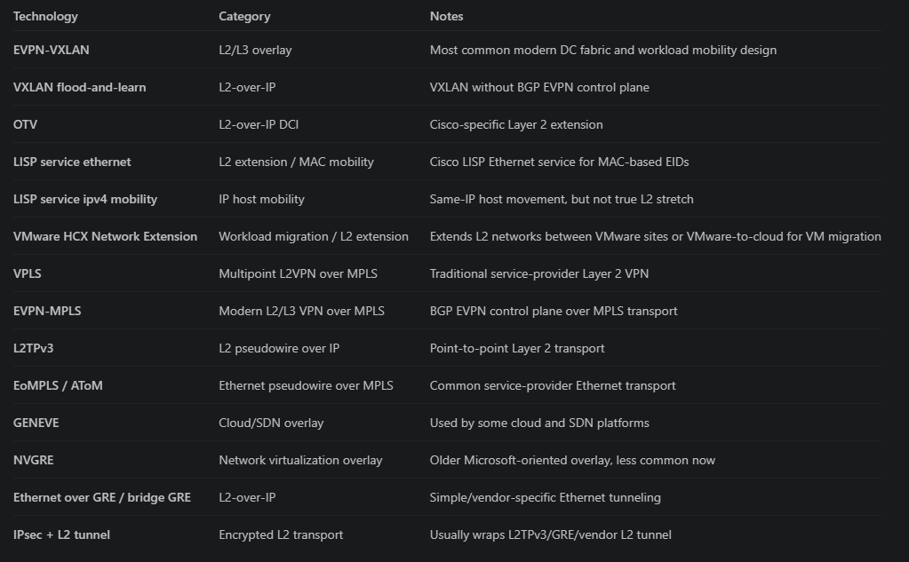
Next, you would need a Network Virtual Appliance (NVA) deployed in the cloud that can use those technologies. Basically, you will need a virtual machine running router software which can be from OCI Partners like Cisco or Juniper or, if you’re really brave, you can build your own router on Linux.
However, even if you find the right Virtual Router, you will find out there some limitations to supported technologies or the combination of router + technology + cloud network will simply not work. The purpose of this blog is to showcase at least one of the technologies in the table working on Oracle Cloud.
Cisco Catalyst 8000v on OCI
Cisco supports Catalyst 8000v on OCI which makes it a great candidate for testing Layer 2 extension architectures. Out of the table above, we will focus the discussion on two Cisco proprietary technologies:
a) OTV – Cisco’s Overlay Transport Virtualization might have been a good fit but the OCI Catalyst 8000v image does not support VLANs (as it is a router) so, naturally, OTV will not work.
b) LISP – Cisco’s Cisco Locator/ID Separation Protocol is an overlay routing technology that separates an endpoint’s identity from its current network location. It maps EIDs such as host IPs, prefixes, or MACs to RLOCs, which are the reachable tunnel router addresses. This allows traffic to be tunneled to where an endpoint currently resides, enabling use cases like routed overlays, host mobility, and in some modes Layer 2 extension.
Cisco LISP can be configured in multiple ways to give us the required functionality, however only one mode will actually work.
a) LISP in mode ethernet – while this would have been the go-to, this will not work because it needs the router to support actual VLANs which the cloud c8000v does not.
b) LISP in mode IPv4 + IP host mobility – while this is not true Layer 2 extension, this will provide the illusion of extension to your network and make communication possible.
Cisco LISP with IP Host Mobility
We can use this technology to fool your network into thinking the cloud subnet is in the same Layer 2 domain as a VLAN in your datacenter. This will work very well for OCVS VLANs but using it for Oracle native subnets is extremely complicated and limited. However, the purpose of this blog is to show that it can be done even though it is not recommended because of the added complexity.
To understand the configuration, we need to dig a little deeper into Cisco LISP. While this is not intended as a LISP training, we need to discuss some of the details of the configuration. Basically, LISP requires multiple services running on a node, as below:
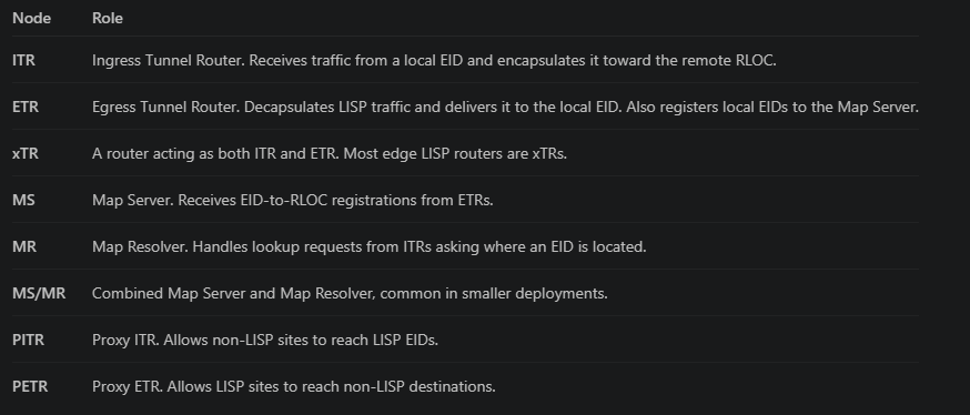
You can spread the services across multiple nodes in your network. However, for the purpose of this blog, I will only use 2 routers:
- The Datacenter side router will be: xTR+MS/MR
- The OCI side router will be: xTR
- PITR and PETR are not covered in this blog but will likely be needed in a production deployment.
Note that the Cisco Catalyst instance must run in Autonomous mode and have a DNA Advantage license applied.
Implementation for OCI Native subnets
Let’s look at a diagram:
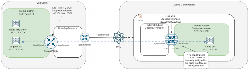
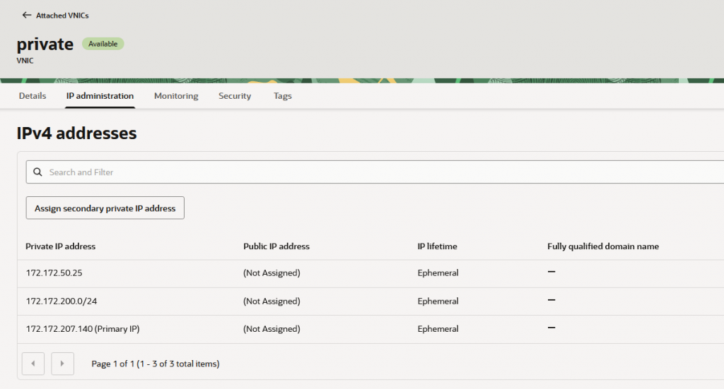
If you plan to implement this on an OCI native subnet there is one caveat that will make it complicated, operational wise. In short, even if all the setup is working properly from CISCO’s point of view, the OCI network layer must be told about your on-prem host IPs. This is required because broadcast is not supported in the native subnet and is done by assigning the on-prem host IPs to the Cisco interface, on the Oracle side. There are some limits here:
- You can add up to 63 secondary addresses on the c8000v interface which will be mappings of your datacenter hosts.
- The secondary addresses can be /32 host IPs which means you can have up to 63 hosts in the datacenter VLAN that was extended to the cloud, that can be reachable.
- The secondary addresses can also be ranges in a CIDR notation. This means that you can have virtually unlimited hosts in the datacenter side, as long as you can group them into a summary CIDR.
On the Oracle side, you need to assign all datacenter IPs as Secondary IP addresses on the C8000V interface, as below:
Implementation steps:
- Create an underlying Layer 3 network connection from your datacenter to the cloud. This can be FastConnect, IPSEC or even Internet.
- Deploy the Cisco c8000v in OCI with one interface for the underlying connection and one interface in the subnet that will be the extension of your datacenter subnet.
- Apply the provided configuration.
Notes on the configuration:
- The provided configuration is for example only, you will need a Cisco Specialist to refine it to your needs.
- The configuration is for LISP only, does not show the routing needed for the underlying connections. You will need to create the route rules to allow the Loopback interfaces to communicate. This can be static routing or any dynamic protocol.
- Most likely, any extended subnet to the Cloud will need to communicate with other subnets not part of LISP or simply to the Internet. In this case, the architecture can become even more complicated and it is not covered in this blog.
Also, showing the OCI side network constructs (route tables, security entries) would make this blog too long. Suffice to say, communication must be allowed on all layers.
Configuration example:
! =========================
! ON-PREM ROUTER (xTR + MR/MS)
! =========================
interface Loopback1
ip address 100.100.100.100 255.255.255.255
interface GigabitEthernet1
description Underlay
ip address 10.1.1.10 255.255.255.0
interface GigabitEthernet2
description LAN
ip address 172.172.0.10 255.255.0.0
lisp mobility subnet1 nbr-proxy-reply requests 3
router lisp
locator-set localsite
100.100.100.100 priority 1 weight 100
exit-locator-set
service ipv4
itr
etr
map-server
map-resolver
itr map-resolver 100.100.100.100
etr map-server 100.100.100.100 key cisco123
exit-service-ipv4
instance-id 0
dynamic-eid subnet1
database-mapping 172.172.0.0/16 locator-set localsite
exit-dynamic-eid
service ipv4
eid-table default
exit-service-ipv4
exit-instance-id
site DATA_CENTER
authentication-key cisco123
eid-record 172.172.0.0/16 accept-more-specifics
exit-site
exit-router-lisp
! =========================
! OCI CLOUD ROUTER (xTR)
! =========================
interface Loopback1
ip address 200.200.200.200 255.255.255.255
interface GigabitEthernet1
description Underlay
ip address 10.2.1.10 255.255.255.0
interface GigabitEthernet2
description extended_subnet
ip address 172.172.207.140 255.255.0.0
lisp mobility subnet1 nbr-proxy-reply requests 3
router lisp
locator-set OCI
200.200.200.200 priority 1 weight 100
exit-locator-set
service ipv4
itr
etr
itr map-resolver 100.100.100.100
etr map-server 100.100.100.100 key cisco123
use-petr 100.100.100.100
exit-service-ipv4
instance-id 0
dynamic-eid subnet1
database-mapping 172.172.0.0/16 locator-set OCI
exit-dynamic-eid
service ipv4
eid-table default
exit-service-ipv4
exit-instance-id
exit-router-lisp
Note: this example is for extending one subnet only however you can add as many subnets as you want, provided that the OCI side c8000v has a dedicated interface for each.
Important note: In OCI, each subnet created reserves the first IP for routing purposes. This means that you MUST not use that IP in your datacenter as it will overlap with the OCI side and you may experience issues. In my example, where the extended subnet is 172.172.0.0/16, IP 172.172.0.1 is reserved by OCI and must not be in use in your datacenter.
Implementation for OCI OCVS VLANs
The implementation for using this with OCVS VLANs is almost the same, with one important difference: OCI VLANs support broadcast so you no longer need to assign the DC IPs to the Cisco Interface. This makes the implementation much better as it takes away a big operational load.
The diagram will become:
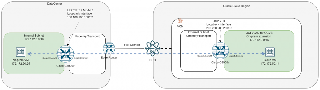
Note: As described in this blog, OCVS workloads can use either NSX segments or OCI Native VLANs.
- For NSX segments use VLAN extension with HCX, a native VMware solution, described here: https://blogs.oracle.com/cloud-infrastructure/l2-network-extension-from-on-premises-vmware-environment-to-oracle-cloud-vmware-solution-using-vmware-hcx
- For VLAN deployments you can use the constructs described in this blog.
One final note
As said multiple times, extending your datacenter subnets to the Cloud is not a best practice and should not be considered a desired end-state architecture. However, if it becomes a migration requirement, this blog hopefully provided some insights on how that could be accomplished.
And this concludes this blog. I hope it helps you!