Last month, the OCI Development team for OCI Network Firewall launched the Source Network Address Translation (SNAT) configured through NFW policies. The SNAT feature is a well required feature since it can resolve some of our customers’ use cases. In the lines below I will highlight one such use case that was requested many times. Prior to SNAT on OCI NFW, some other third party expensive solutions were adopted, however, now we can implement it using the OCI native service which provides native redundancy and management.
We can create firewall policies with NAT rules for Source Network Address Translation on outgoing traffic. It will work by changing the source IP address of the traffic using a pool of SNAT from the internal network. Thus, the destination VM will see as source IP address, an internal “safe” IP address.
When the NAT policy is enabled, the NAT pool is allocated from the firewall’s subnet only. You need to ensure for the 4 Gbps OCI NFW shape at least four IP addresses are available for SNAT and for 25 Gbps shape at least five. NAT rules are evaluated based on the priority allocated and processed in a sequential order. The first matching rule will be applied.
Important to note:
- Currently only IPv4 SNAT rules are supported
- The OCI NFW can perform private SNAT operations only, public SNAT and DNAT are not supported
- After a firewall policy containing NAT Rules is attached to a firewall, NAT can’t be disabled (toggled off) on that firewall. To disable NAT, you must first update the firewall with a policy that doesn’t include NAT rules. Only after this update can the NAT can be disabled on the firewall.
- When applying NAT rules, they’re applied in a specific order within the rule operations. NAT rules are applied after decryption, security, and tunnel rules
We have a complete guide for the new feature on the OCI NFW at the following web page: About NAT rules
Let’s talk about our use case we want to accomplish with the new SNAT feature on OCI NFW:
– our OCI customer has hired a third party partner for managing one if its environments on OCI
– the connection from the partner on-premises to OCI is done via redundant IPSec tunnels (all the traffic must be encrypted)
– the customer is not allowing any source IP address to manage the environment other than the ones assigned to the Security VCN (where the OCI NFW is deployed)
– the management connections are only to be initiated from the partner network to the servers running in customer’s managed VCN
An obvious feature we can use to design the new connectivity request is the SNAT on the OCI NFW.
The network topology we use to highlight the above points is listed next:
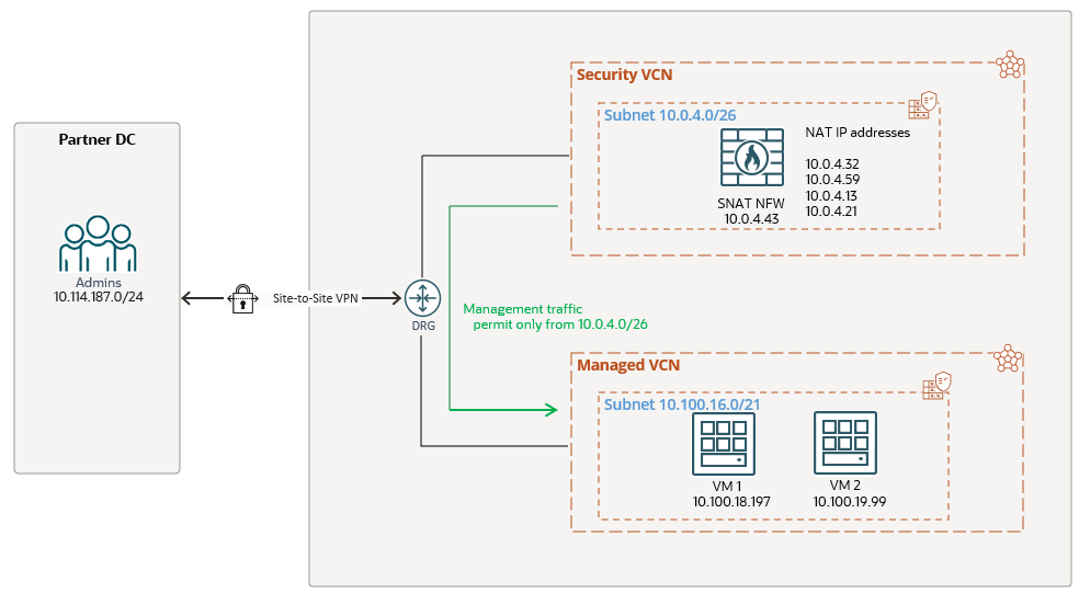
The management traffic source IP addresses must be from the range of 10.0.4.0/26, the CIDR designated by the customer to be allowed on the Managed VCN. That being said, any source IP address outside of 10.0.4.0/26 will not be allowed and will be blocked on the Managed VCN.
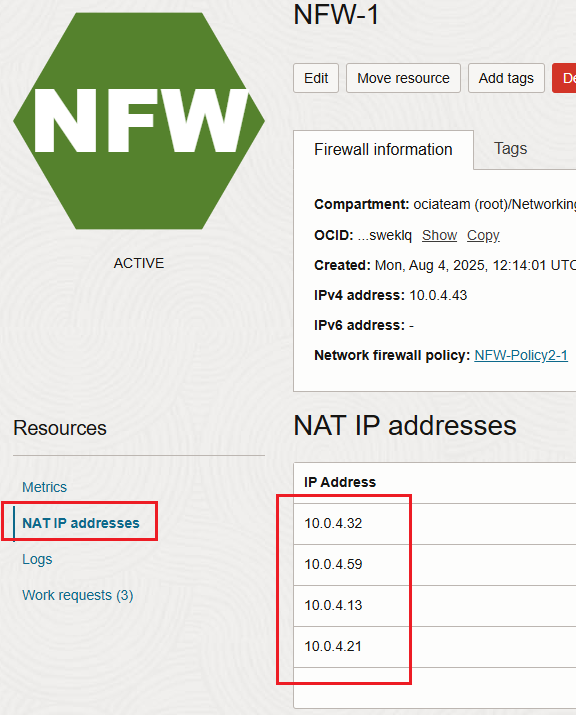
Before starting the SNAT configuration we need to answer a question I’m often receiving, can I specify the IP addresses the OCI NFW will use for SNAT? The answer is the following, when you create the NFW and enable the NAT, the IP addresses will automatically be chosen by the NFW. We cannot control the IP addresses that will be in use by the NFW for SNAT, however we can see those IP addresses in the Web UI after the NFW is created with NAT enabled:
We will not cover the routing configuration part for this networking construct since it was discussed in details here. We will focus our attention only on the NFW SNAT configuration, this is the star of our today’s blog.
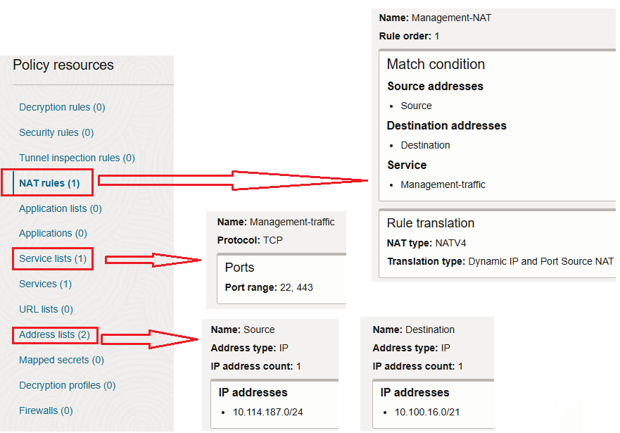
We are going to define our NAT rule by using the following matches:
– source IP addresses: 10.114.187.0/24
– destination IP addresses: 10.100.16.0/21
– services: TCP port 22 and 443
We have the SNAT configuration in place, now, let’s try from 10.114.187.0/24 to reach our managed servers on OCI using TCP port 22 and 443:
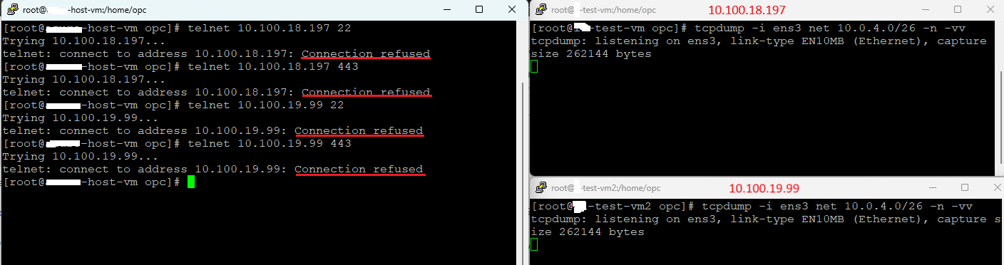
The results are not the expected ones since the connection refused for both ports is prompted. Analyzing the NFW traffic logs:
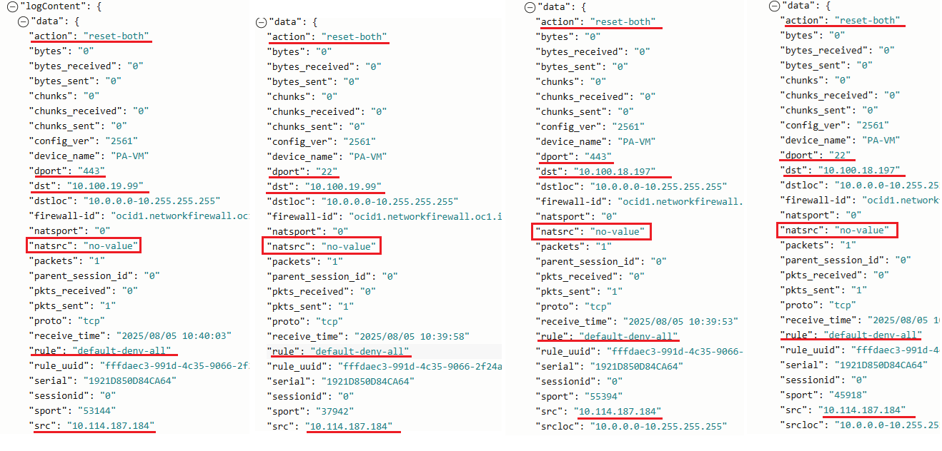
We can see that the traffic on both ports was denied and the rule used by the NFW is default-deny-all. Another important log entry is “natsrc” with no-value which means that our traffic didn’t entered into the SNAT configuration logic. Why is that? The reason for showing it was intentional because on many discussions I had, I was asked if we can use only the SNAT configuration on the NFW and nothing else. Above we explained that that the NAT rules are applied after decryption, security, and tunnel rules. This means that we must have a security rule to accept the traffic first. After the traffic is accepted, then the nat rules will be applied to the traffic. As you noticed in the screenshot above for Policy resources, no security rule was added.
Let’s add the security rule to accept the traffic and try again:
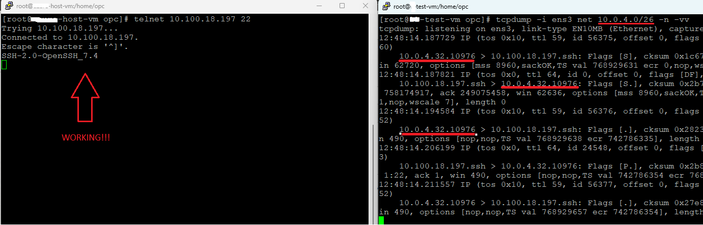
Just look at the packet capture on the destination VM, the source IP address is 10.0.4.32 and if we recall this is one of the IP addresses that will be used by the NFW for NAT.
Where is the information regarding the SNAT in the NGW logs? The answer is below:
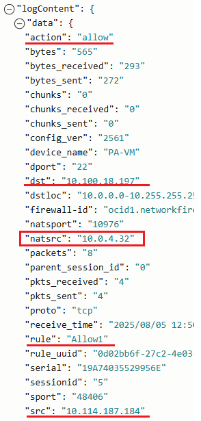
When the security rule is in place and after the traffic is allowed, the NAT rule (if exists) is evaluated. If a match is found (like in our case) the traffic is SNAT-ed. The traffic log lists the rule that allowed the traffic with the “natsrc” containing the IP address that was used by the NFW to SNAT the traffic.