In previous entries of my Cisco FTD blog series, I explored the deployment of Cisco Firepower Threat Defense (FTD) and Firepower Management Center (FMC) in OCI, along with the configuration steps of a site-to-site VPN in route-based mode. This time, I’ll guide you through a different approach on how to configure a site-to-site VPN using policy-based mode on Cisco FTD.
If you’re new to VPN setups with FTD or missed the earlier parts of this series, I recommend checking out my previous blog posts, to get familiar with the core requirements and initial setup.
In writing this blog, I had the pleasure of working with my colleague Raffi Shahbazian, whose insights were invaluable in refining the steps for this blog. A big thank you for your support.
With that being said, let’s dive into how policy-based VPN can be used between Cisco FTD and OCI.
Agenda
- OCI – Create IPsec Connection.
- Cisco – Create a VPN Connection.
- Verification.
Create IPsec Connection
Log in to the OCI dashboard, navigate to the networking section, from the Customer Connectivity list click on Site-to-Site VPN, Create IPSec connection.
Choose the proper name, compartment, and Dynamic Routing Gateway.
Continue with tunnel1 configuration, check the screenshot below.

Note: You don’t need to add routes to your on-prem network with policy-based VPN, so no static routes required to be added here.
Note: The customer-premises equipment (CPE) vendor could be Cisco policy-based or other.
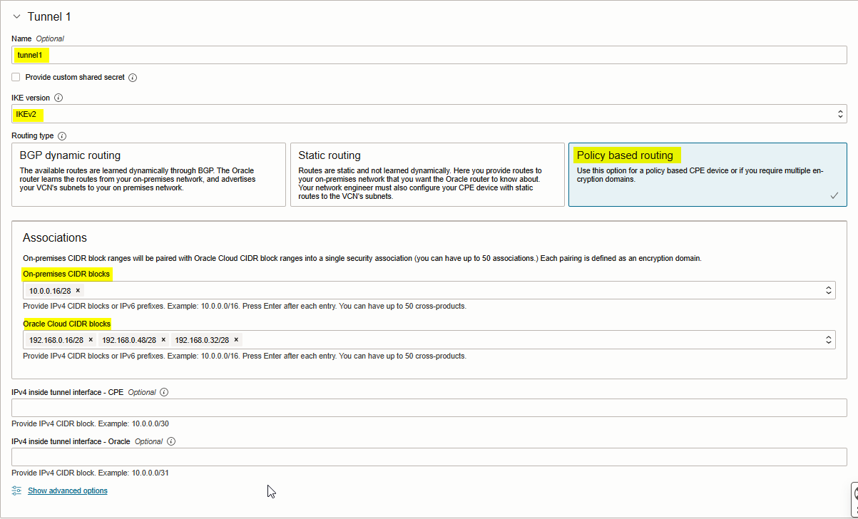
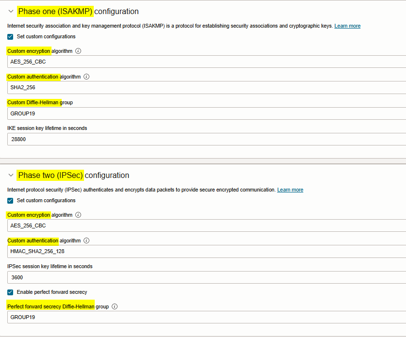
Note: Click Show advanced options if you need to customized phase one (ISAKMP) and phase two (IPSec) tunnel config. Please check the screenshot below.
Click Create IPsec Connection.
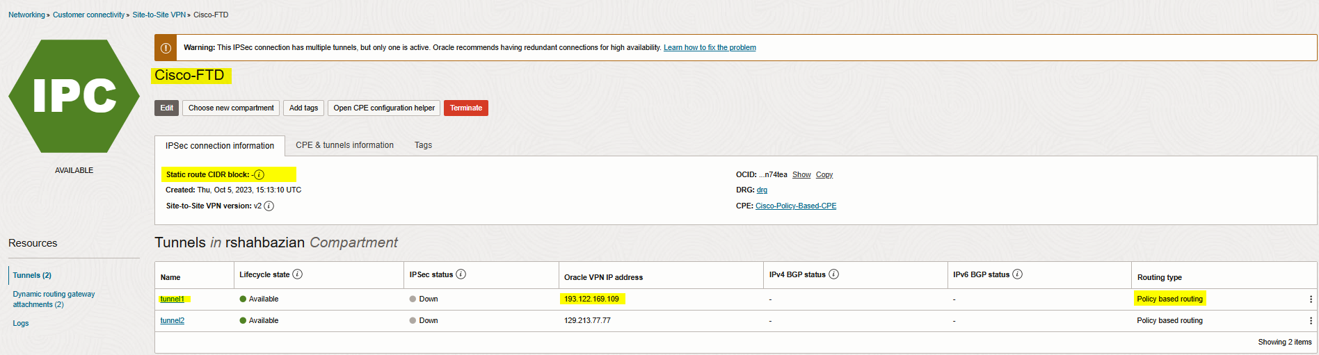
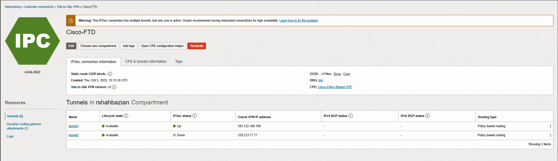
The IPsec connection is created and displayed on the page. The connection is in the provisioning state for a short period.
Now, click on Open CPE configuration helper, create content, and download configuration.
Note: You need to save the Oracle public IP address, and Shared secret.
Create a VPN Connection
Connect to you Cisco FMC, navigate to Devices, VPN, and Site to Site VPN.
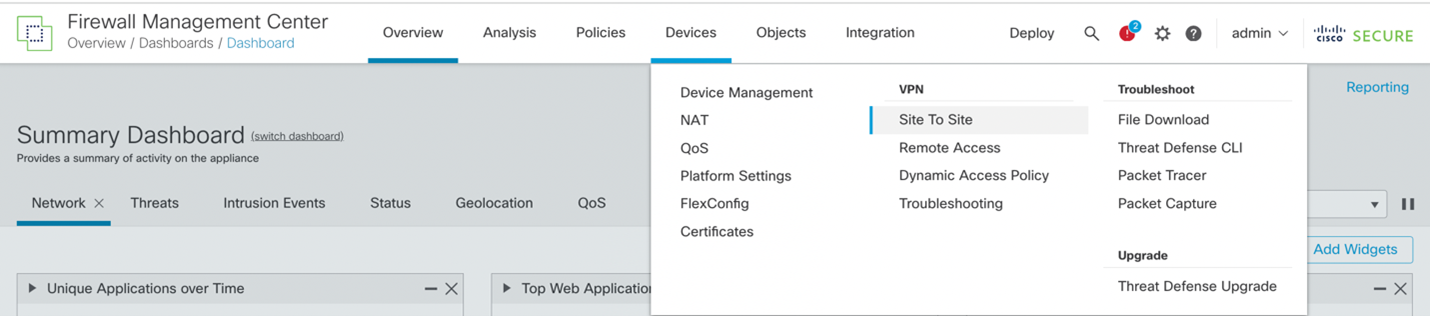 Select + Site to Site VPN to add a new IPSec VPN connection.

Most of the configuration will be under the Create New VPN Topology section.
However, prior to configuring the VPN Topology section, we’ll need to define the extended access-lists that will be used by the policy-based VPN for the ISAKMP (phase 1) and IPSec Policy (Phase 2).
Extended Access-Lists
To configure the extended access-lists that will be used by the policy-based VPN, we’ll need to navigate to the Objects -> Object Management -> Access Lists -> Extended -> Add Extended Access List. We’ll need two extended access-lists:
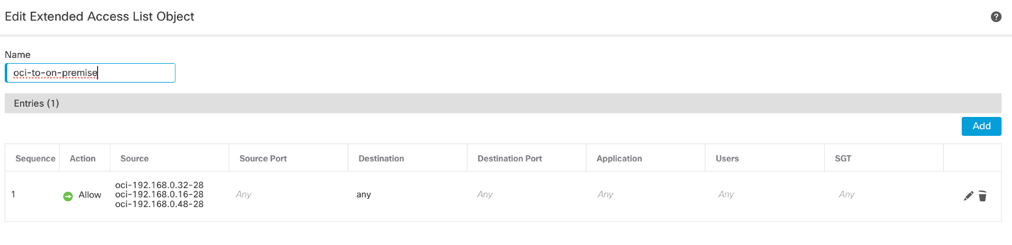
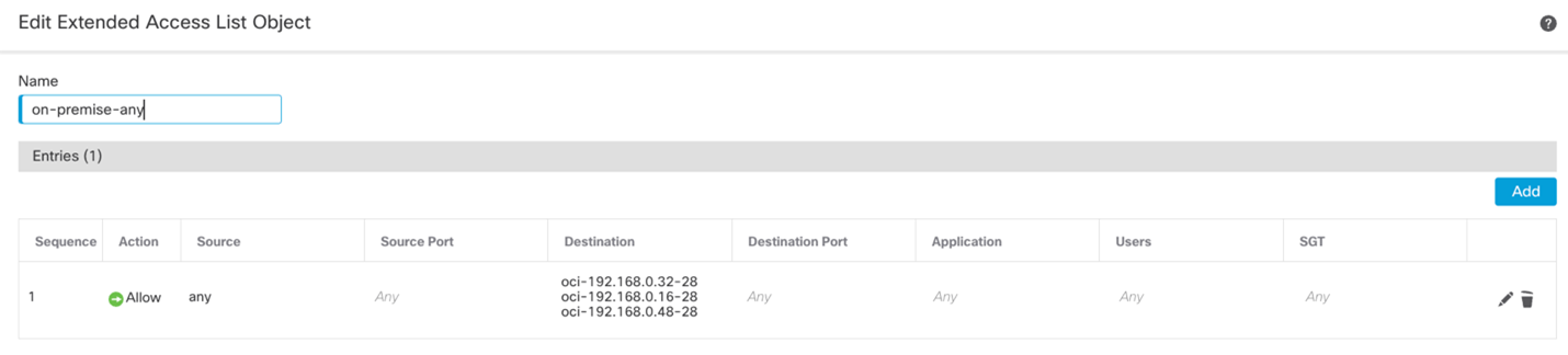
One to identify OCI to On-Premises traffic. The other to identify On-Premises to OCI traffic.
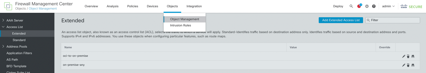 In my case, I have created the following extended access-lists: oci-to-on-premises and on-premises-any.
ISAKMP and IPSec Policy
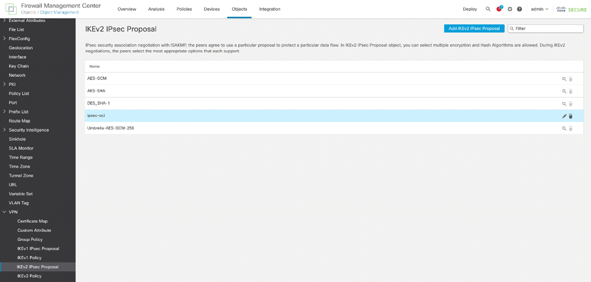
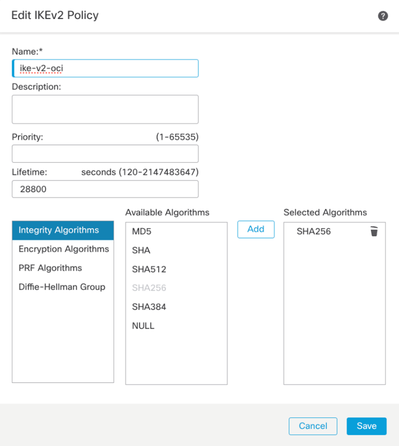
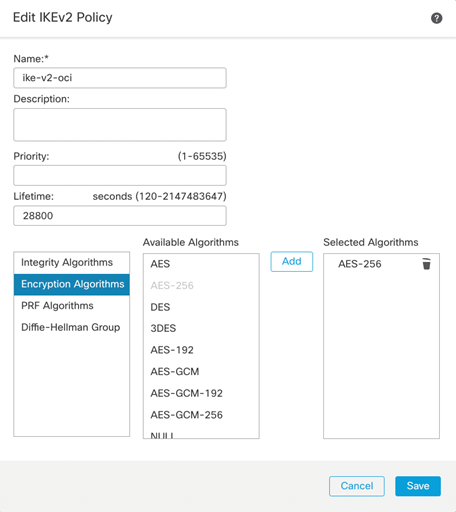
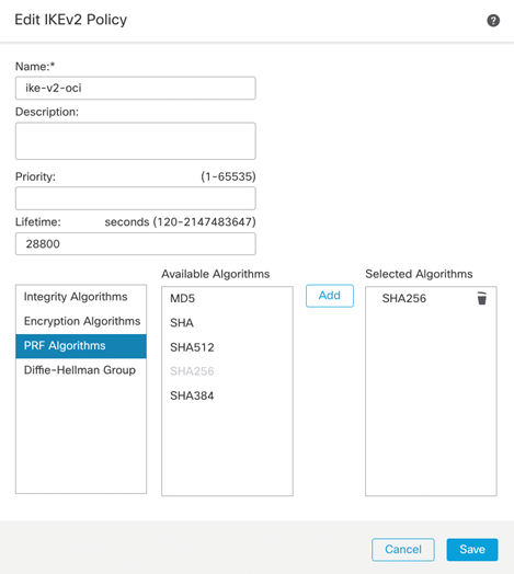
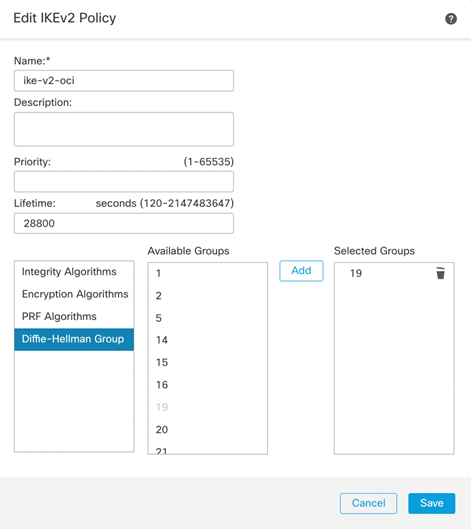
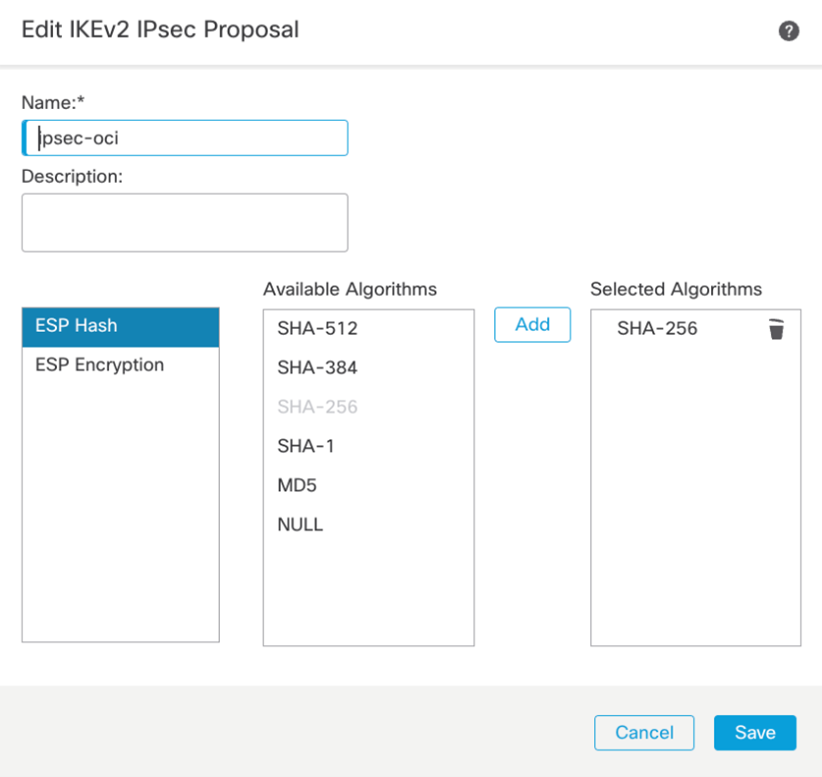
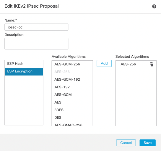
To configure the IKE and IPSec Policy, we’ll need to navigate to the Objects -> Object Management -> VPN. Depending on which version of IKE you are using, you will need to create the proposals for the respective IKE version. In my case, I am using IKEv2 and will use the IKv2 Policy and IKEv2 IPsec Proposal to manage the cipher suites.
IKEv2 Policy
IKEv2 IPSec Proposal
Now we have all the configuration requirements and can start to configure the VPN.
Navigate to Devices, VPN, and site-to-site VPN.
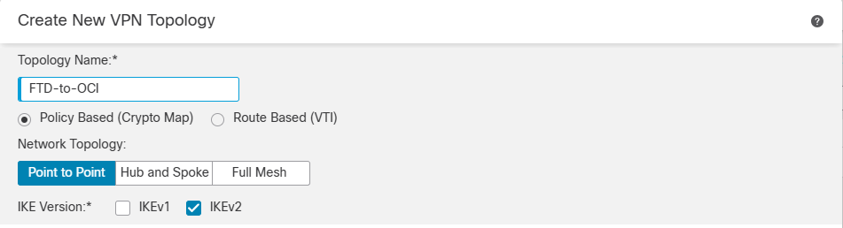
We will need to provide the following parameters to properly configure a policy-based VPN with OCI:
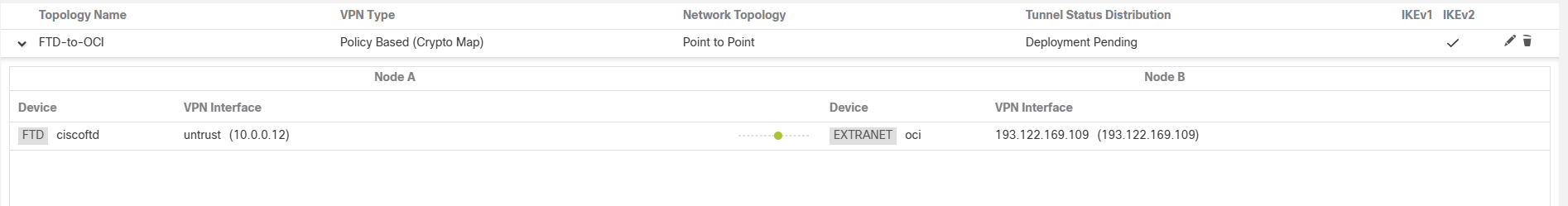
Topology Name: Name of the connection
Network Topology: Point to Point
IKE Version: Select either IKEv1 or IKEv2. This must match with the configuration in OCI. In my case, I am using IKEv2.
Endpoints Tab – Node A and Node B.
IKE Tab – IKE related parameters
IPSec Tab – IPSec related parameters
Advanced Tab – Advanced settings
Note: Please check the screenshots below.
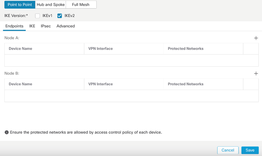
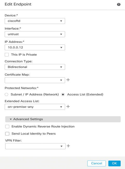
Let’s create endpoints starting with Node A, Cisco FTD.
Note: 10.0.0.12 IP is the FTD untrust (outside) Gateway.
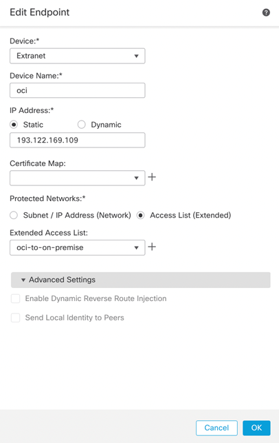
Node B (OCI).
Note: 193.122.169.109 is OCI tunnel1 public IP address.
Endpoint final look.
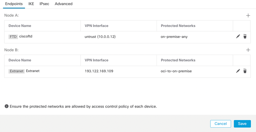
We will continue with configuring tables, IKE, IPsec, and Advanced. Please check the screenshots below.
Note: Phase one and two tunnel configurations must be match with what you configured from the OCI side.
IKE Tab
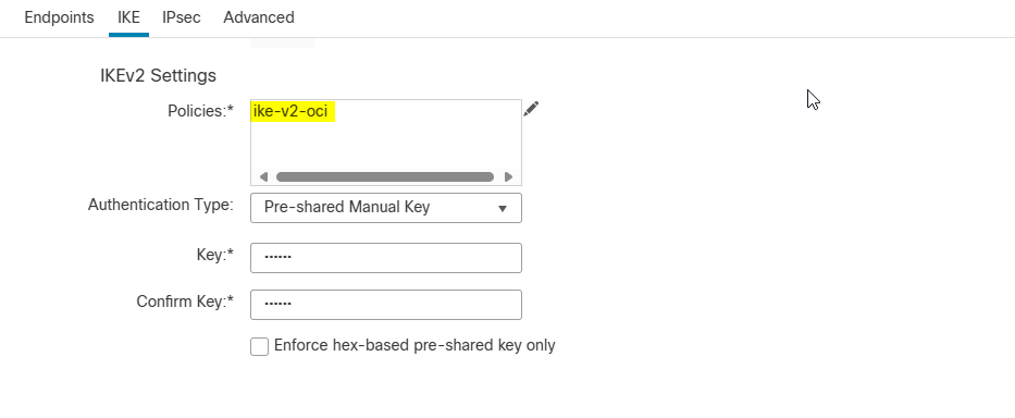
Note: choose Pre-Shared Manual key as an Authentication Type and match key with OCI side.
(Refer to the downloaded configuration document from OCI).
IPSec Tab
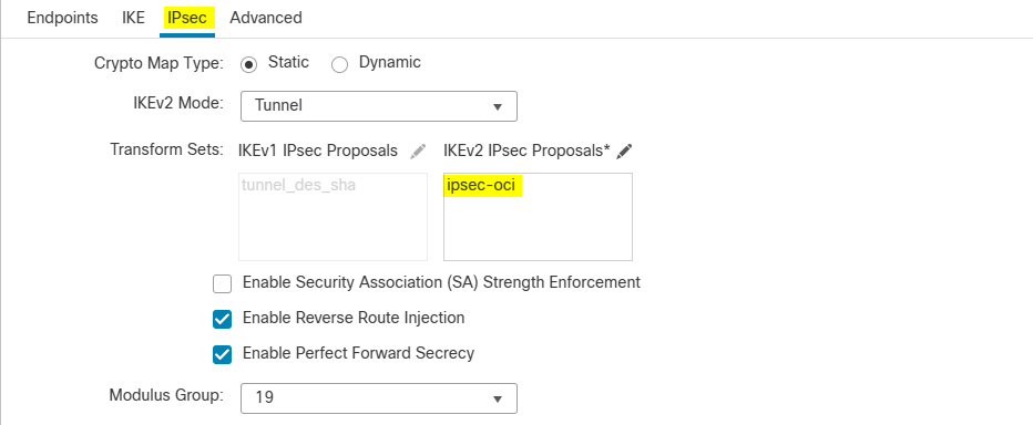
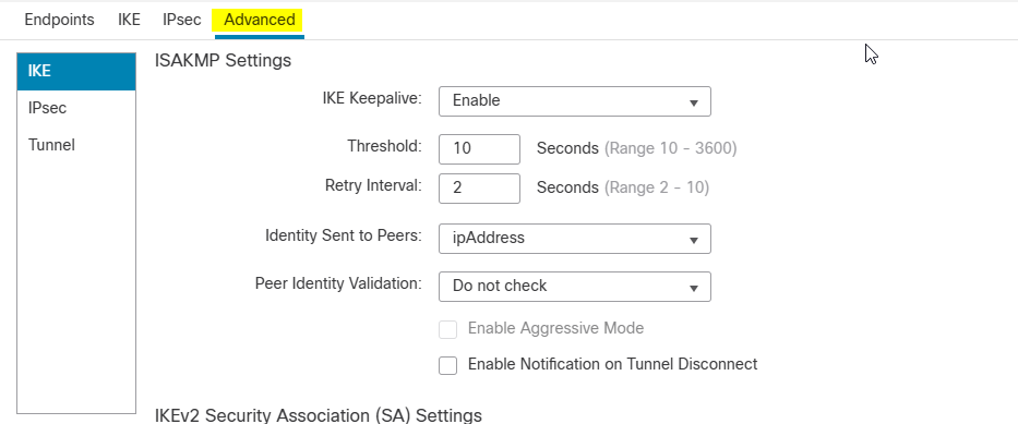
Advanced Tab
IKE sub-tab
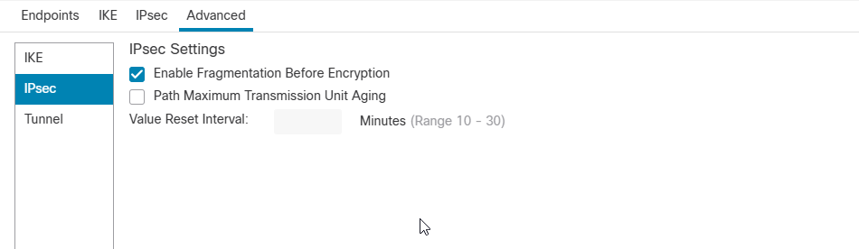
IPSec sub-tab
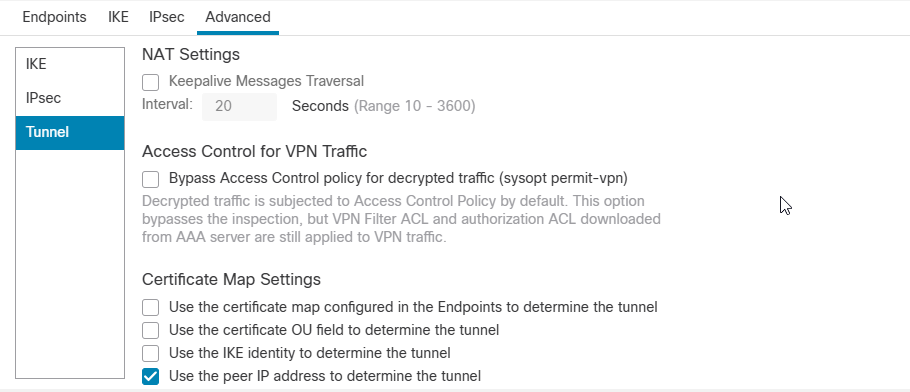
Tunnel sub-tab
Click Ok and Save.
At this point you should see the tunnel status is Active and Up from FMC and OCI side.
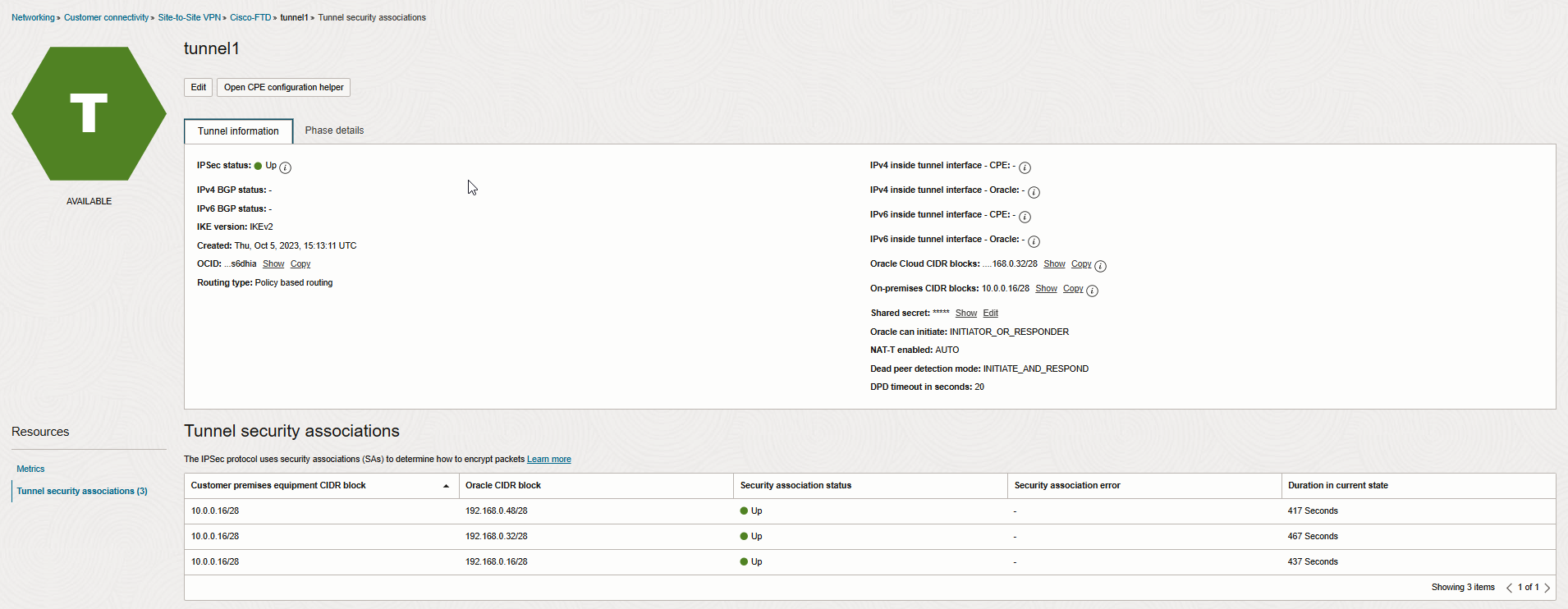
Let’s check the Tunnel security associations (Phase2) to see what traffic selectors are forming the tunnels.
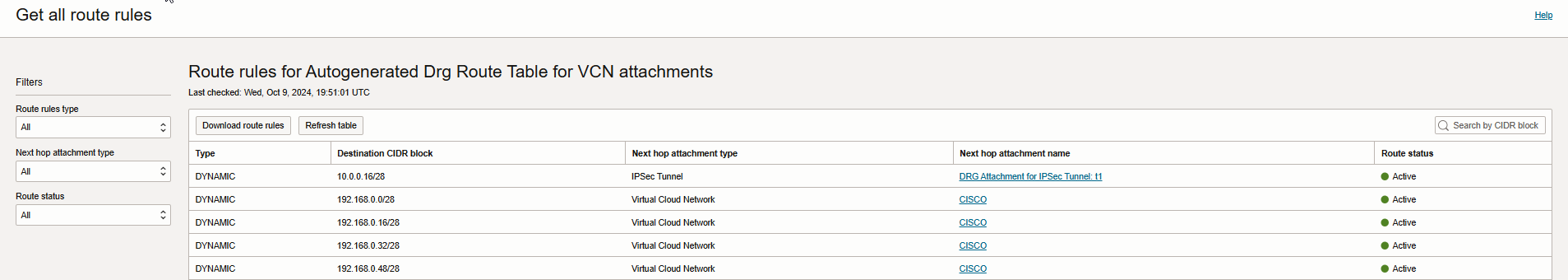
And here is the Get all route rules page for Autogenerated Drg Route Table for VCN attachment.
As you see, we are dynamically learning the on-premises CIDR block (10.0.0.16/28) through IPSec tunnel Drg attachment.
Verification
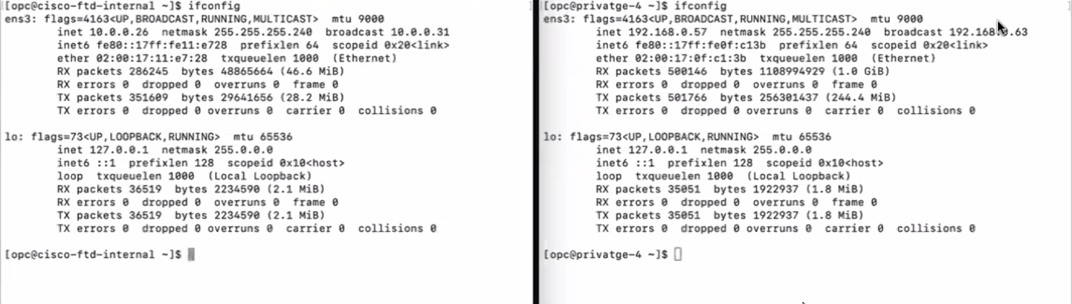
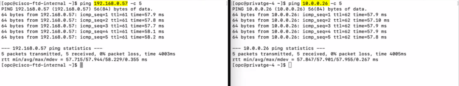
I have created two VMs from both sides (On-prem and OCI) for testing purposes. Please check the Screenshot below.
I hope you enjoyed it.