

Introduction
This post is the third part of a 3-part blog series about connecting multiple OCI VCNs via Megaport using the AS Override feature. The focus of this page is to configure the infrastructure in Megaport. You will need to have the OCI-side configuration completed before attempting the Megaport configuration. To access the main page of this series, please visit this link.
Topology
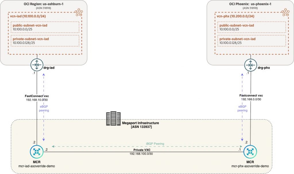
For the purpose of this demo, we will be creating 2 Megaport Cloud Routers (MCRs) – one in Ashburn and one in Phoenix. These will be used to terminate the FastConnect virtual circuits from their respective OCI regions and they will also BGP peer with the DRGs in those regions. Additionally, the 2 MCRs will also be connected to each other via a Virtual Cross connect (VXC) and iBGP peered with each other.
** Note that both FastConnect circuits could have also terminated on a single MCR. However, we are using two to emulate a larger enterprise network which may have multiple MCRs which land OCI FastConnects among other circuits.
Pre-Requisites
The goal of the blog is to focus on the connectivity through Megaport. Hence, the following OCI resources are assumed to have already been created.
- Virtual Cloud Networks (VCN) in both regions, Phoenix and Ashburn
- Subnets within this VCN
- Route tables and Routes within the VCN
- Security Lists allowing access between the VCNs
- Dynamic Routing Gateway (DRG) in both regions
- VCN attachments between the VCN and DRG in both regions
- Compute Instances in both VCNs to be used for testing
Furthermore, you will need IAM permissions in OCI for configuring FastConnect circuits and permissions in Megaport for creation of MCR, VXC and for editing settings.
Configuration Steps
Login to the Megaport portal at https://portal.megaport.com. Navigate to ‘Services’ on the left side. If you already have any services deployed, you will see them here else it will be blank

Ashburn side configuration
MCR creation
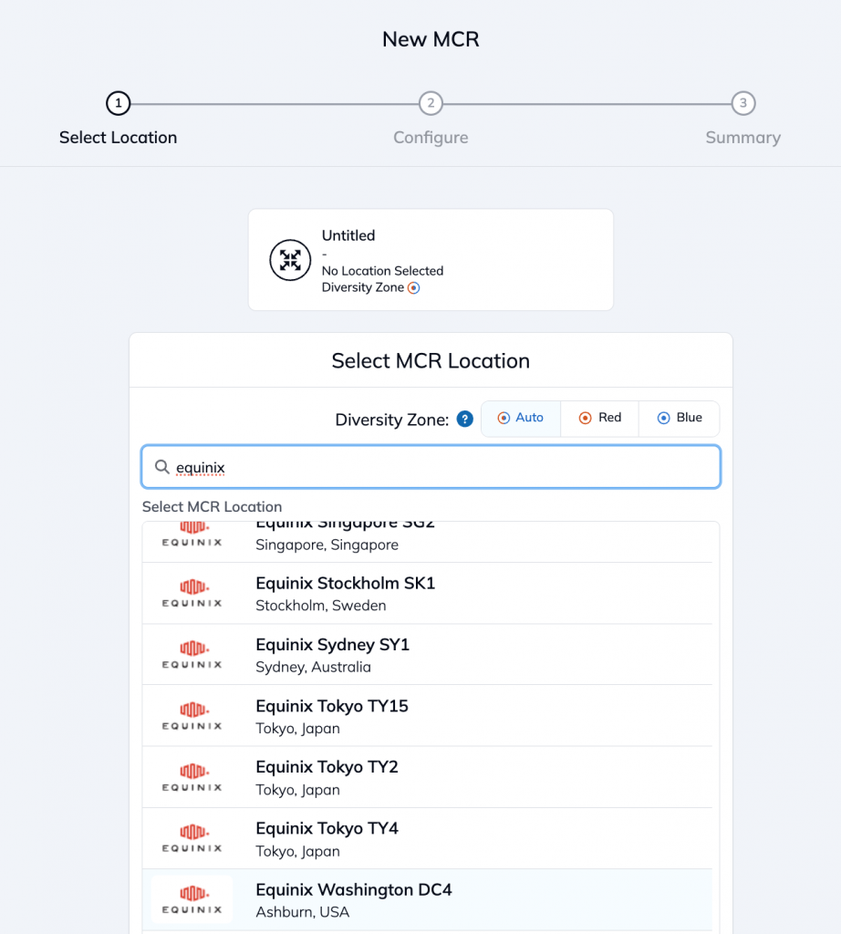
For Ashburn, we will deploy an MCR in the Equinix DC4 datacenter. Click on ‘Add Service’ and then search for Equinix DC4 and select it.
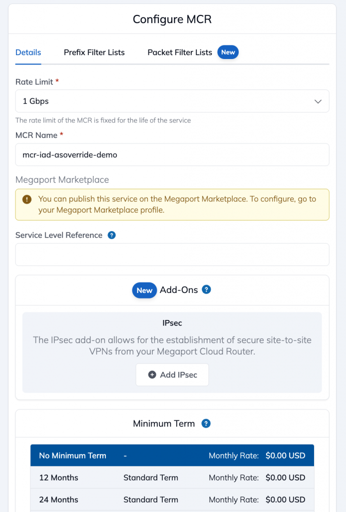
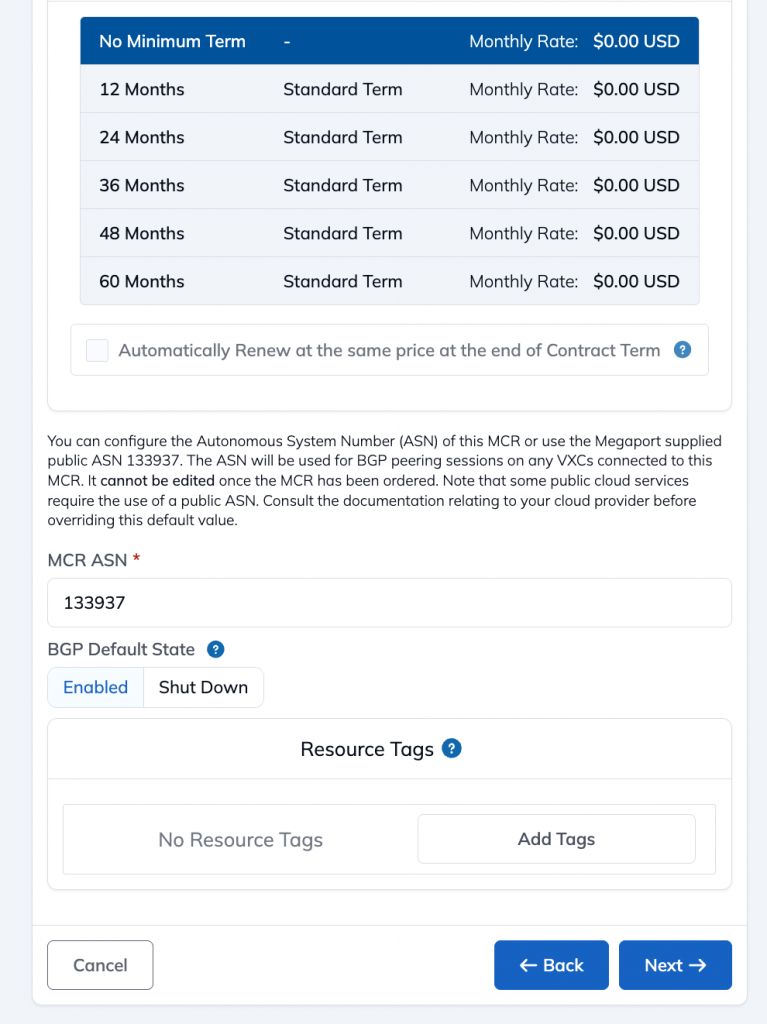
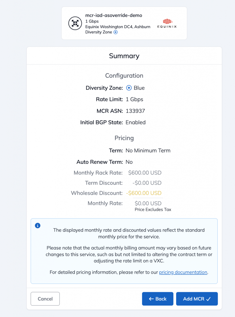
Enter the name of the MCR and select values for speed, billing terms etc. and the BGP ASN to be used for the MCR. In this case, we are using 133937 which is Megaport’s default.
Review the selected settings and then click on ‘Add MCR’
On the Services page, you should now see the created MCR.

Virtual circuit creation
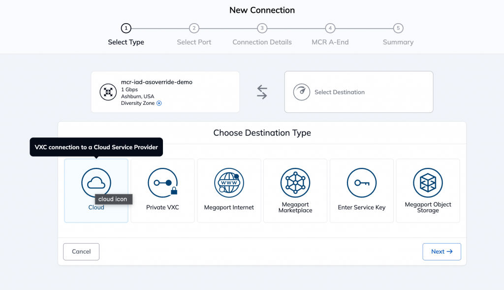
In order to create a connection from this MCR, click on the ‘+’ icon under connections (see on the far right side of the previous image)
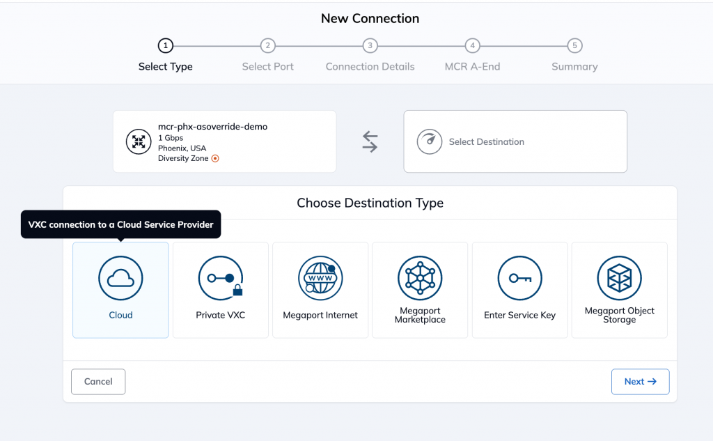
It will open the following page. Since it is a VXC to the cloud, select cloud as the Destination Type.
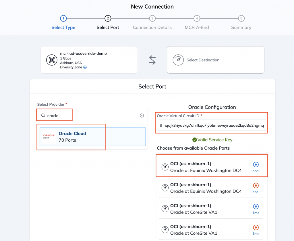
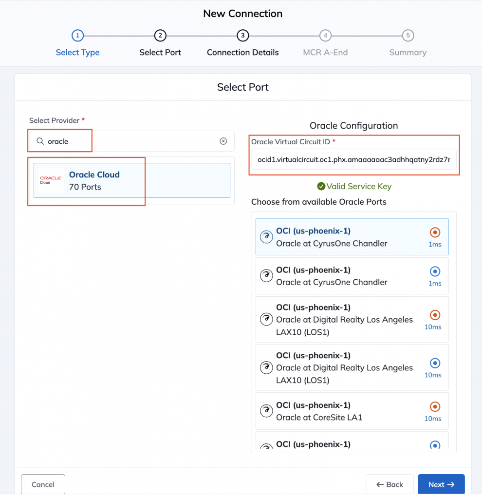
Next, select Oracle Cloud from the Provider and paste the OCID of the FastConnect virtual circuit. The key will be validated after which you can select an Oracle port at a facility of your choice to terminate the VXC
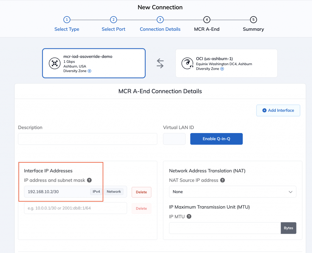
Thereafter, enter the IP address for the interface on the MCR for this VXC
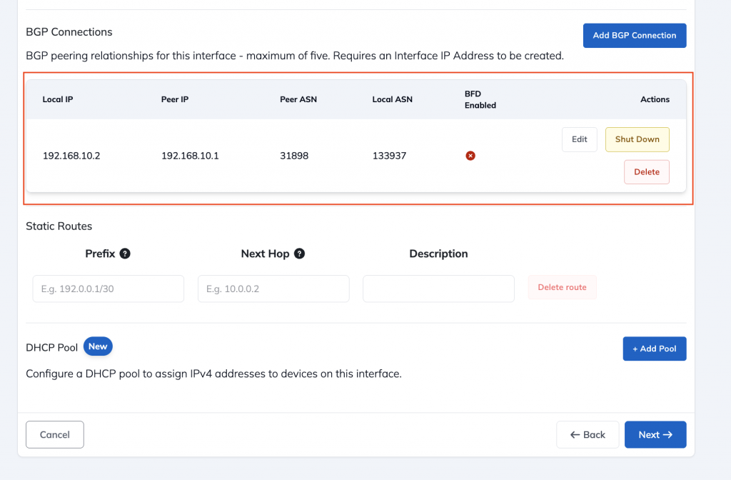
Finally, you configure the BGP peering configuration where the Local IP is the interface IP on the MCR and the Peer IP is the other IP in the same subnet. The Peer ASN for OCI will be 31898. You can choose to enable Bidirectional Forwarding Detection (BFD) but in this example, we have chosen to leave it off.
Phoenix side configuration
MCR creation
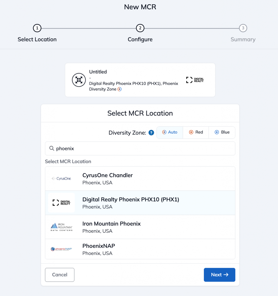
In Phoenix, we will create an MCR in Digital Realty PHX10 location in the Megaport portal
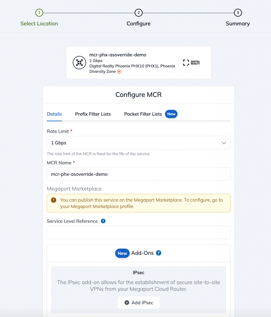
Select the parameters for the MCR, similar to how we did it in Ashburn.
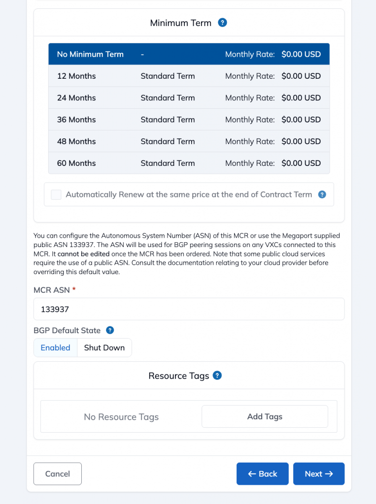
The BGP ASN for the Phoenix MCR will also be 133937 (Megaport default). Thus, the two MCRs will be part of the same AS.
Once the MCR config is done, click on the ‘+’ icon under Connections to add a virtual circuit on this MCR.

It will open the following page. Once again, select Cloud and then Oracle Cloud and enter the OCID of the virtual circuit for the FastConnect from Phoenix.
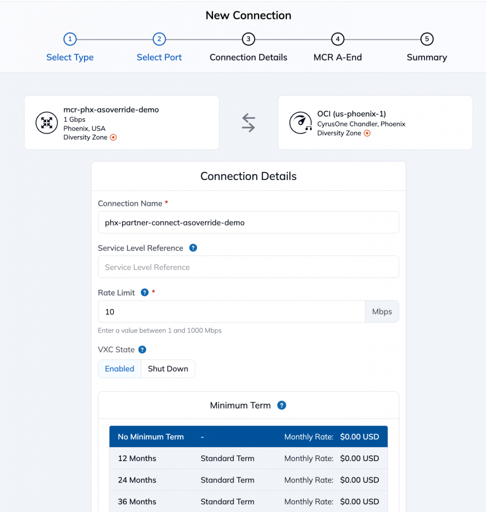
Enter the details of the virtual circuit and agree to contract terms as desired. Local IP will be 192.168.0.2 on the MCR end as per our topology with local ASN of 133937.
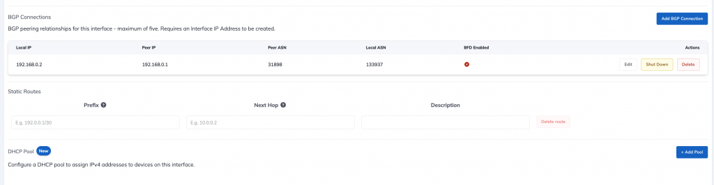
Finally, you configure the BGP peering configuration where the Local IP is the interface IP on the MCR and the Peer IP is the other IP in the same subnet. The Peer ASN for OCI will be 31898. You can choose to enable Bidirectional Forwarding Detection (BFD) but in this example, we have chosen to leave it off.
Inter-MCR Link configuration
The final connection which we need to make is the link between two MCRs.
Lets start on the Phoenix side. Go back to the ‘Services’ page on the Megaport Portal and find the MCR in Phoenix. Click on the ‘+’ icon on the far right to add another connection.
Select Private Virtual Circuit under ‘Destination Type’
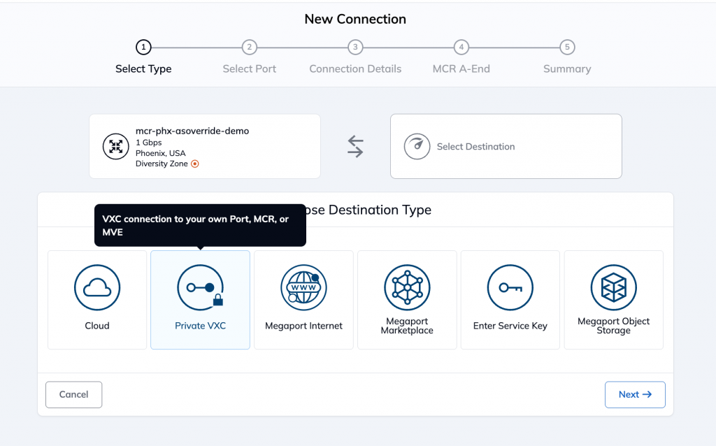
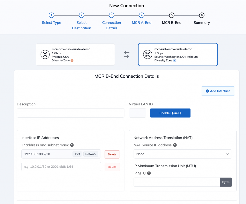
Select the Ashburn MCR as the other end of the connection. Enter details for the local addressing. We are using 192.168.100.0/30 for the inter-MCR link with 192.168.100.1 on the Phoenix side and 192.168.100.2 on the Ashburn side
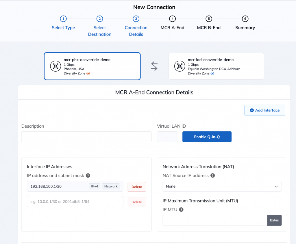
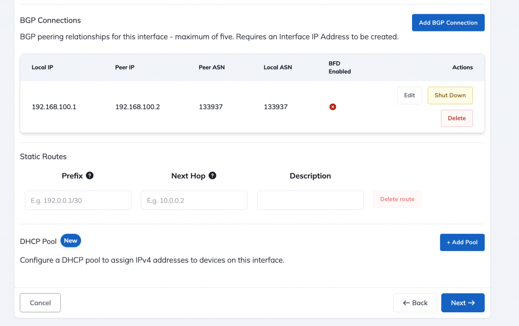
Configure the BGP peering the Phoenix end and click on next.
Next, configure the IP address and BGP configuration Ashburn side of the connection
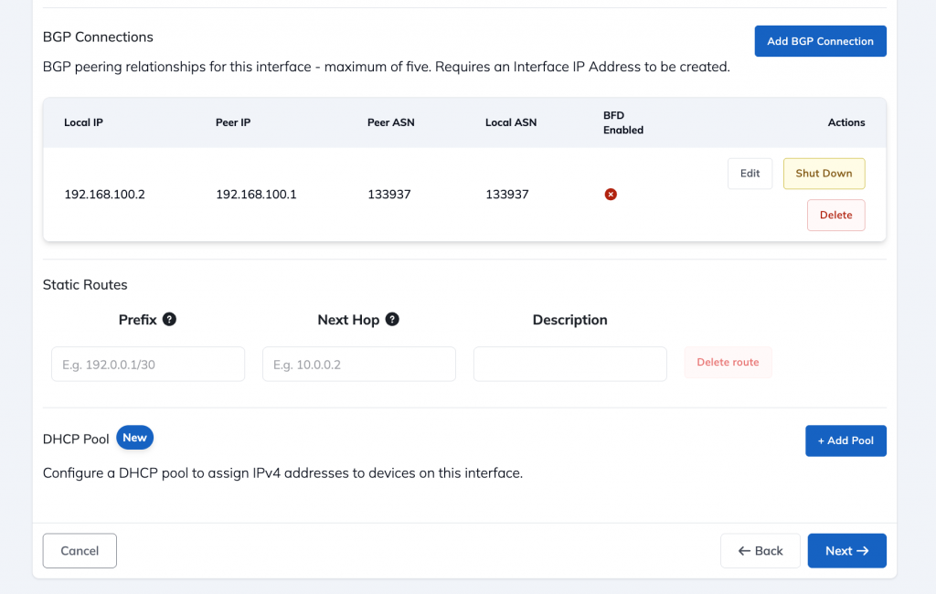
Finally, all the components in the topology have been designed. Remember that this is just the design part of the setup. You can now submit the order on the Megaport after which it will be provisioned and actually deployed. This can take between 15-30 mins.
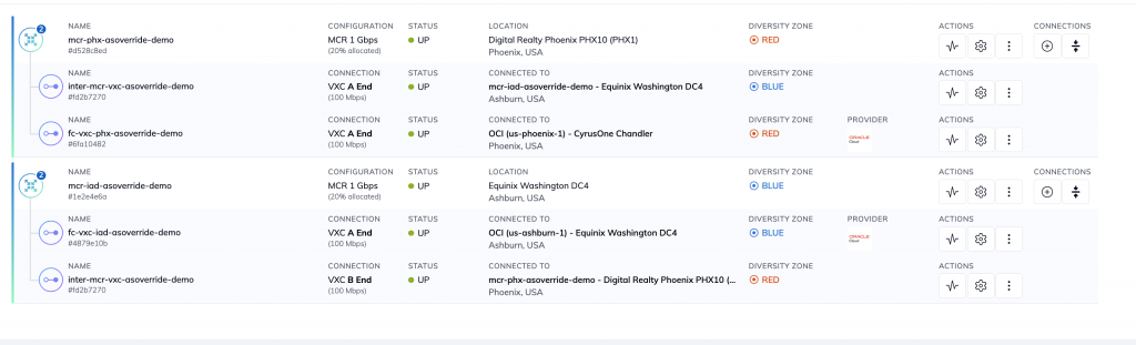
After Megaport has completed the configuration, you should see the status of all MCRs and circuits as UP on the Megaport portal, as seen below:
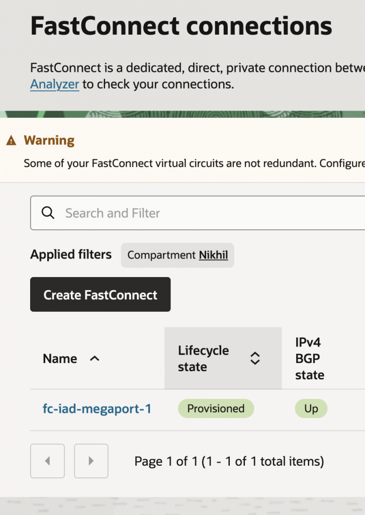
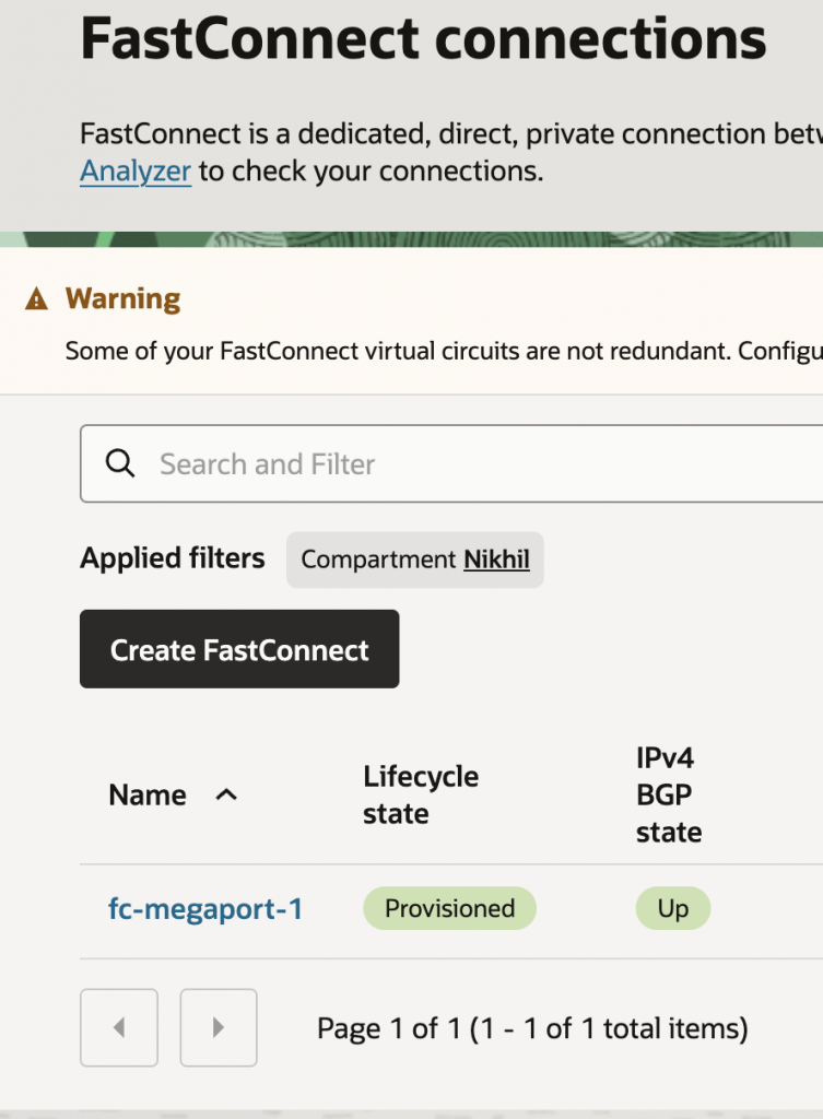
Additionally, you should also see the FastConnect virtual circuits as Provisioned with BGP showing UP on the OCI Portal. For reference, screenshots have been provided below.
Ashburn FastConnect:
Conclusion
This completes the Megaport-side of the configuration. Please return to the main page of this blog series to see how AS Override can help solve the BGP route-exchange issue with this topology.