- The CIS compliance checking script is not impacted. Users should continue using it to determine tenancy compliance with the CIS OCI Foundations Benchmark.
- Users looking for a deployment experience similar to CIS Landing Zone should now use OCI Core Landing Zone, where the same features are available. OCI Core Landing Zone evolves CIS Landing Zone and complies with CIS OCI Foundations Benchmark.
- Users looking for a deployment experience based on fully declarable and customizable templates should use the Operating Entities Landing Zone or the OCI Landing Zones Modules in the OCI Landing Zones GitHub organization.
In my prior blog CIS OCI Landing Zone Quick Start Template Version 2, I discussed how the Landing Zone has an updated networking module that allows the deployment of multiple network architectures. In this blog post I am going show you how to deploy the Landing Zone for network security partners. Before we get to deployment let’s start with reviewing the below architecture.
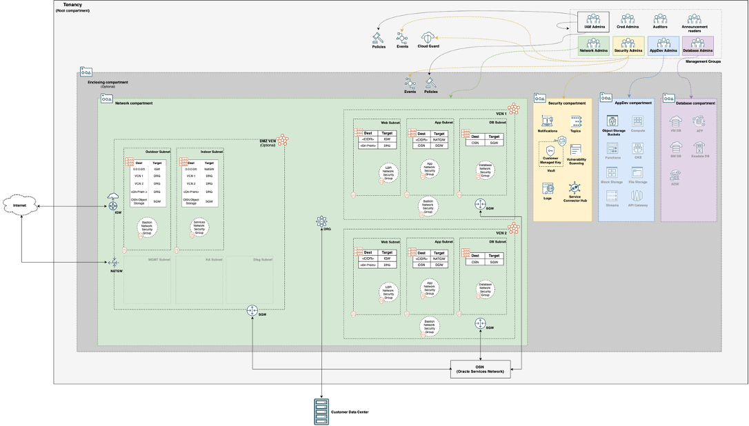
When deploying network firewalls in the Landing Zone the DRG Attachments are not created for any of the VCNs (Virtual Cloud Network) because this is done by security partner Terraform code. Their Terraform will create the DRG Attachments for the VCNs and route the traffic through the security partner network appliances creating a choke point. The only routing the Landing Zone will do is the spoke VCN routing. This choke point will be used to monitor traffic in and out of OCI as well as between VCN spokes. Each partner requires a different number of subnets in the DMZ VCN, you can use the below chart to determine how many subnets you will need in your DMZ VCN:
| Security Partner | Number of Subnets |
| Check Point | 2 |
| Cisco | 5 |
| Fortinet | 4 |
| Palo Alto Networks | 4 |
Now we are ready to deploy!
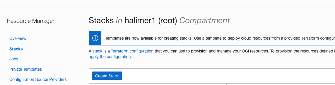
First, we need download a copy of the Landing Zone code which is available here. For this blog post I am going to use Oracle Resource Manager and deploy the Landing zone in the root compartment, but you could also use another compartment as well as use the Terraform CLI.
1. Go to the Resource Manager and select Stacks
2. Click Create Stack
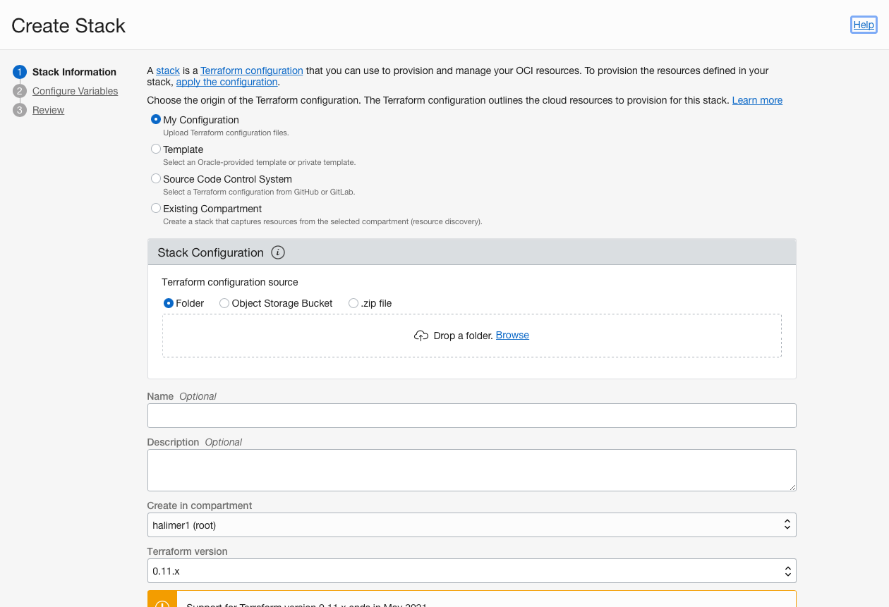
3. Select .zip file and upload the oci-cis-landingzone-quickstart-main.zip
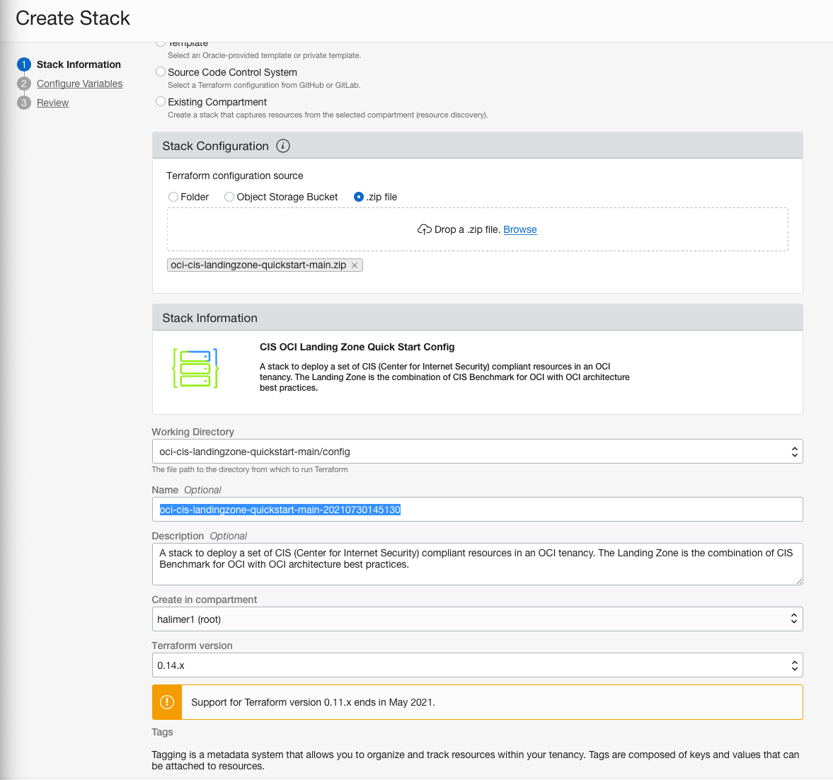
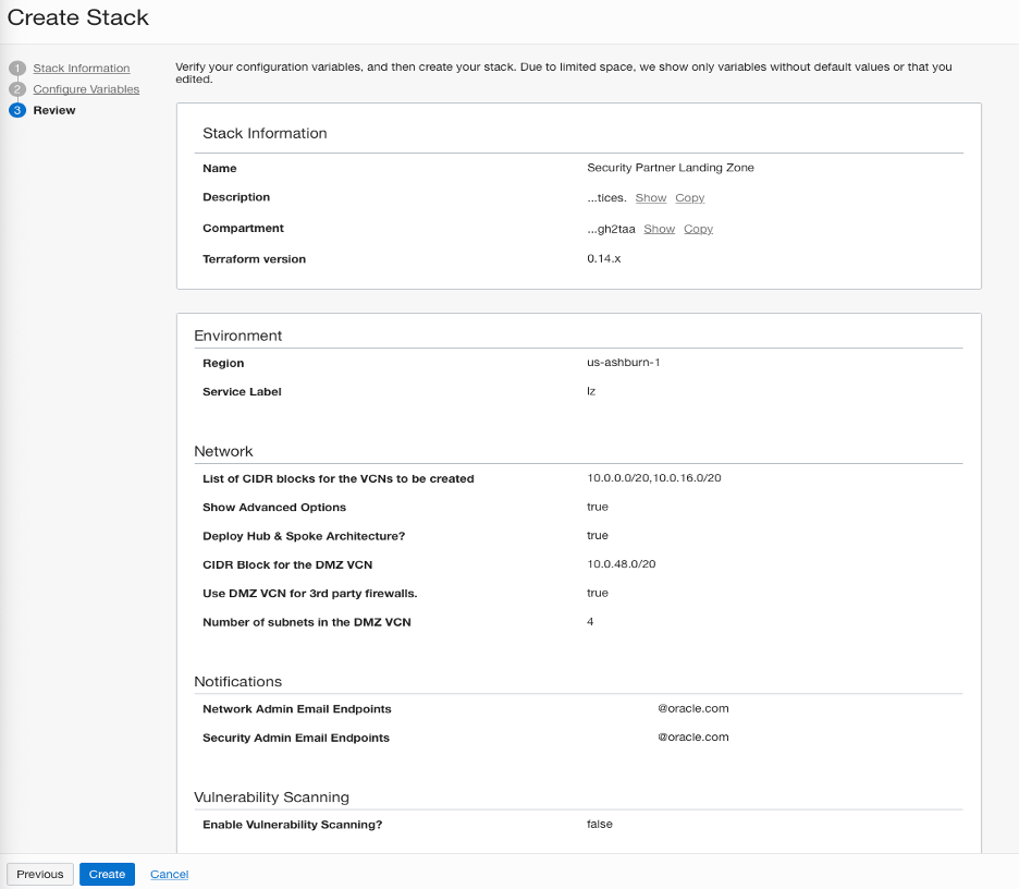
4. Fill in a Name for the stack
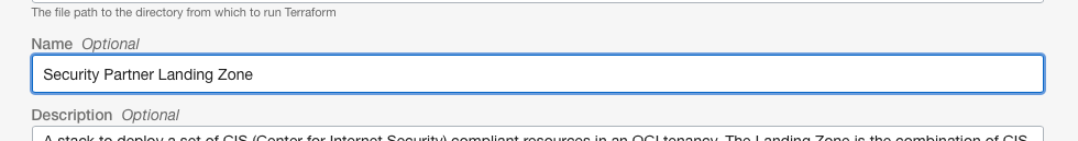
5. Click Next
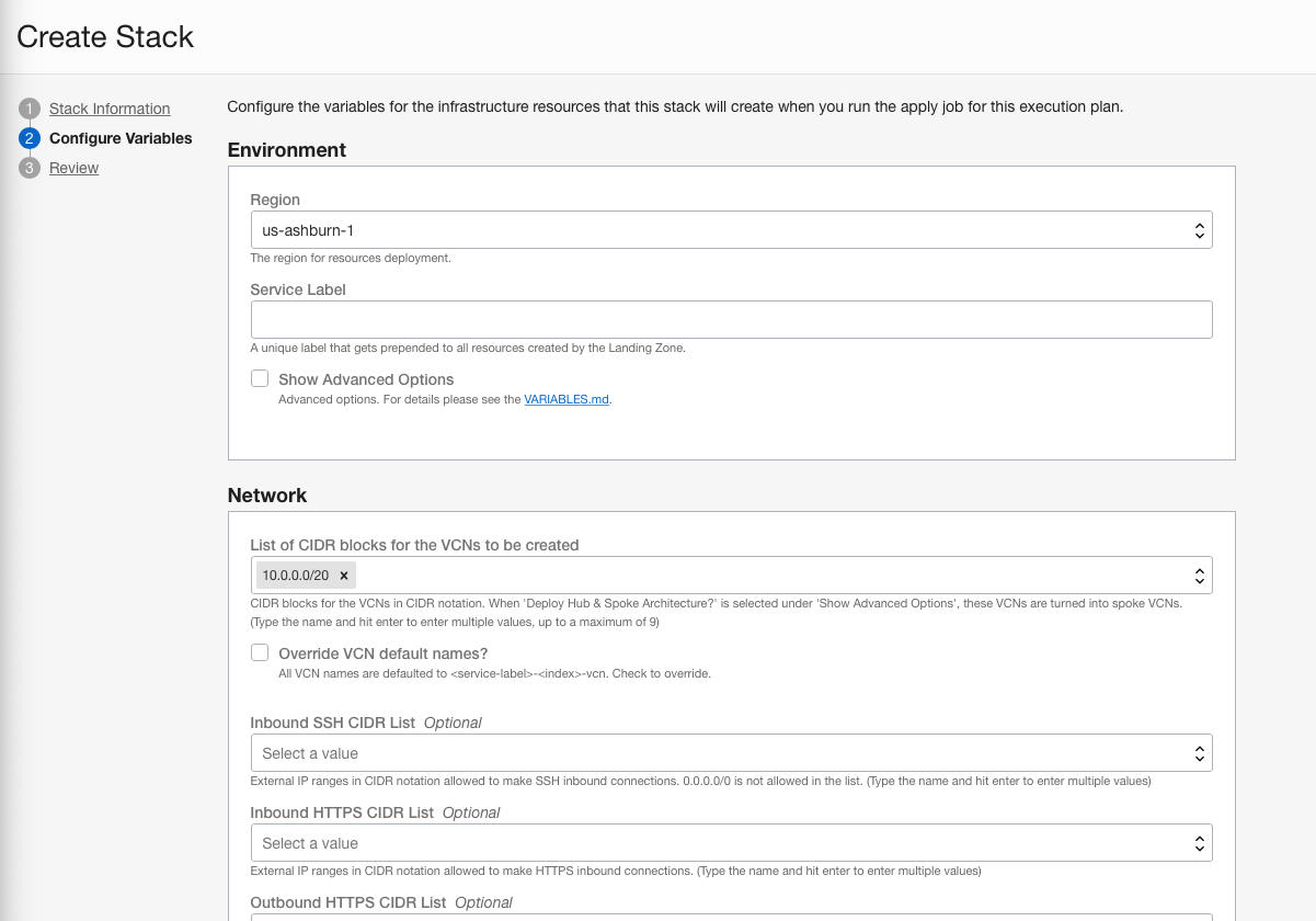
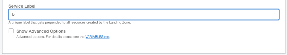
6. Enter a Service Label
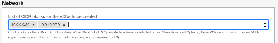
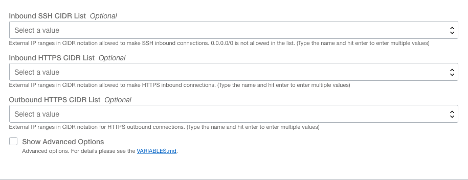
7.Enter one or more Spoke VCNs in List of CIDR blocks for the VCNs to be created
8. You can choose to fill in the Optional fields
9. Select Show Advanced Options
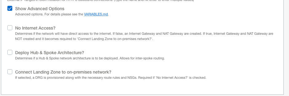
10. Select Deploy Hub & Spoke Architecture?
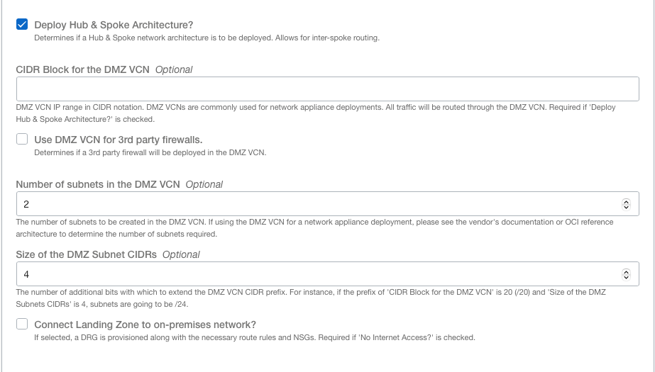
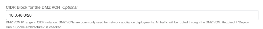
11. Enter a CIDR Block for the DMZ VCN
12. Select Use DMZ VCN for 3rd party firewalls

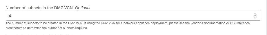
13. Enter Number of subnets in the DMZ VCN (based on security partner requirements above)
14. Enter the rest of the required values
15. Click Next
16. Click Create
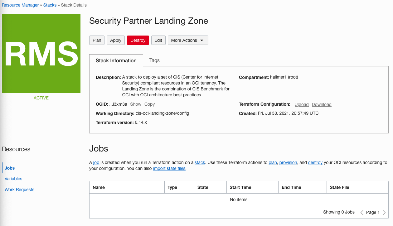
17. Click Apply
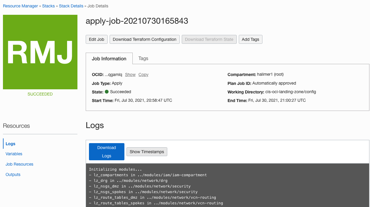
Once the Stack succeeds you are now ready to deploy the network security partner of your choice in the Landing Zone’s DMZ VCN. To deploy your security partner read the blog Adding our security partners to a CIS OCI Landing Zone . If you want to learn more about how to configure the networking in the Landing Zone take a look at the VARIABLES.md.