Prerequisites:
OCI Network Firewall – Concepts and Deployment
OCI Network Firewall – NAT Gateway use case
OCI Network Firewall – Securing the LBaaS traffic
In the early days after OCI launched the Network Firewall we had a very comprehensive discussion about the OCI Network Firewall, its functionalities, configuration options and capabilities. The prerequisites listed above are important for the context of this blog.
This blog will be centered on design considerations when the NFW is requested by our customers to inspect East-West and North-South traffic on OCI. Why the design considerations are important? More specific, where we should place the OCI NFW for Ingress and Egress Internet traffic? This is one of the most received NFW networking design questions, where to place it when we deal with Ingress and Egress Internet traffic. The answer to this question is important since it can lower the overall cost of the solution. Having a design optimized from the costs perspective offering the desired level of security is a good path to follow.
In this blog, I do not have the intention to present OCI NFW specific configuration, rather I will center the discussion on two main simple networking topologies for Ingress and Egress Internet traffic.
Note: The concepts does not apply for VCN to VCN or VCN to On-premises traffic inspection because these cases can be accomplished by using specific routes in the route tables.
The problem statement: Can I use just one OCI NFW for Ingress and Egress Internet traffic using default routes toward Internet Gateway and NAT Gateway?
Multiple implementation projects including the OCI NFW for Internet ingress traffic inspection revealed that more than 90% required the OCI VMs to have private IP addresses and front-ended by a Public Flexible LBaaS. Taking into account this is the most used scenario for Internet ingress traffic, we will analyze it shortly.
In the below section we will find out the answer.
1. Placing the OCI Network Firewall before the Public Flexible LBaaS
The following networking topology highlights the OCI NFW placement:
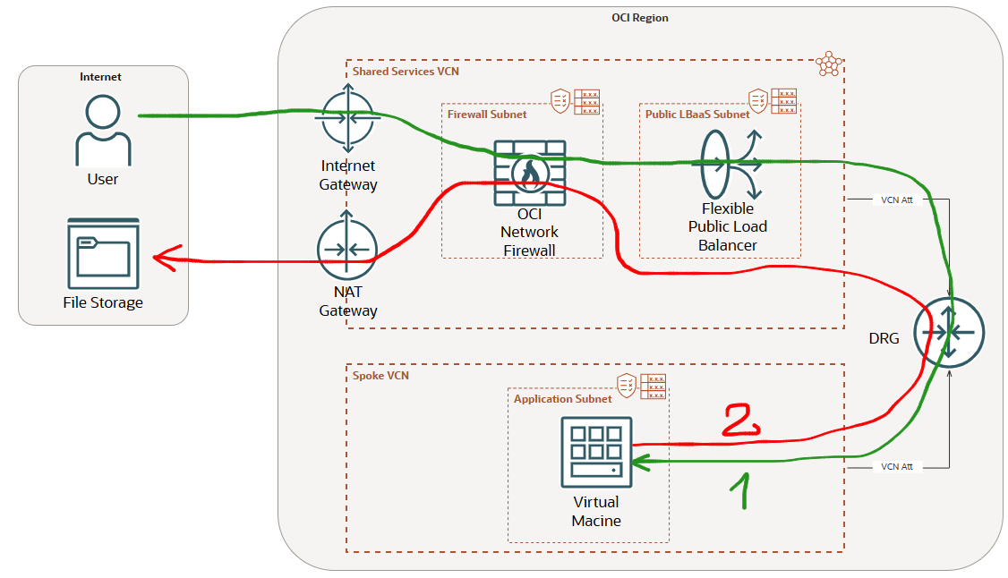
The green line represents the Internet ingress traffic to a Public Flexible LBaas inspected by the NFW placed before the LBaaS. The configuration will required a route table attached to the Internet Gateway configured with a route rule for the LBaaS subnet using the OCI NFW private IP address as next-hop (see the prerequisites blogs).
The red line represents the Internet Egress traffic initiated by a VM in a Spoke VCN that will use the NAT GW from the Shared Services VCN to an Internet File Storage. This traffic needs also to be inspected by the OCI NFW.
We know now the traffic that needs to be handled by the OCI NFW. Let’s have a look at the route table associated with the NFW subnet when the response is sent back to the Internet by the LBaaS and when the VM is initiating the Internet connection through the NAT GW to the File Storage (as we know, both connections needs to be analyzed by the NFW and forwarded accordingly).
The response traffic coming from the LBaaS to the Internet hosts needs to be sent to the IGW and the VM initiated connection to the Internet File Storage needs to be sent to the NAT GW. As we know, we cannot configure two default routes using two different next-hops, in our case the IGW and the NAT GW.
One option in this case is to use a default route with IGW as next-hop and more specific routes to Internet destinations using the NAT GW as next-hop.
This sounds not very difficult in theory, however none of my customers adopted it since it is very hard to track all the Internet destinations for Linux or Microsoft updates or for some other Internet connections through NAT GW.
A second solution is to use another OCI NFW in a separate subnet with a new route table attached and to use it for Internet Egress traffic via the NAT GW.
For sure, the second solution will double the NFW cost since two NFWs will be used. If you want to optimize the overall costs, probably it is not something you will accept.
2. Placing the OCI Network Firewall after the Public Flexible LBaaS
The following networking topology highlights the OCI NFW placement:
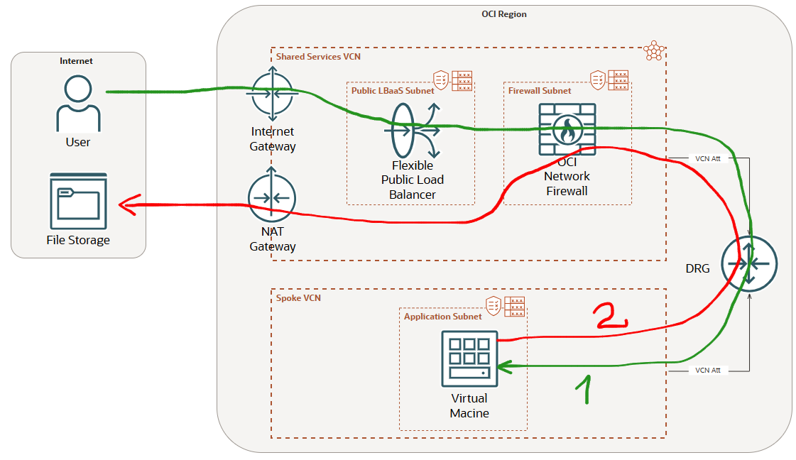
Using the next placement of the OCI NFW, after the Flexible LBaaS, the NFW subnet route table is more flexible. Let’s explain it.
When the LBaaS receives the Ingress Internet connection it is performing the source and destination NAT (SNAT/DNAT). When the traffic is sent by the LBaaS to the backend servers through the OCI NFW, the source and destination IP addresses are private (the source private IP address is the one used the LBaaS to perform the SNAT and the destination is the backend server private IP address from the Application subnet in the Spoke VCN).
When the traffic is returned for the green path and received by the OCI NFW, the destination IP address is the private IP address owned by the LBaaS, thus the OCI NFW subnet route table does not need to contain any route for LBaaS destination (Intra VCN traffic routing). On another hand, when the VM is initiating an Internet Egress session using the NAT GW through the NFW, the NFW subnet route table will contain one default route with the NAT GW as next-hop. As we immediately noticed, we have just only one default route configured and the OCI will not complain at all.
Actually we move the default route using the IGW as next-hop away from the NFW subnet route table and place it in the Flexible LBaaS subnet route table.
The solution is not entirely perfect. Placing the OCI NFW after the LBaaS can limit its capabilities for analyzing the public source IP address of the traffic and enforce the filtering based on the public IP address of the traffic. Hovewer, most of the security features can be configured and used in this scenario.
As a conclusion, if the OCI NFW is placed after the Flexible LBaaS it is able to support both, the Ingress and Egress Internet traffic. This is giving us a very flexible and versatile way to design the cloud networks and include one single OCI NFW for multiple purposes and minimizing the overall cost of the solution.